Home/
Registry/
Ford/
Bronco/
1987-1991/
“Eddie Bauer”/
Photo
supermotors.net/registry/media/1042386
Ford Bronco IAC / Throttle Air Bypass Valve Solenoid Wiring Diagram (C160, S165)

Reference · 1987-1991 BroncoAll 175 wiring diagrams
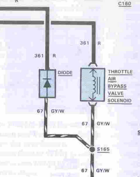
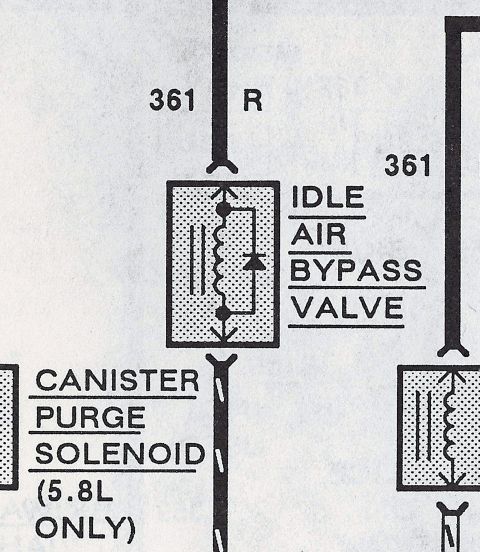



Wiring diagram showing throttle air bypass valve solenoid and diode with circuit 361/67 GY/W wires and splice S165.
Part of 1987-1991 Ford Bronco Wiring Diagrams
This document is a cropped portion of a Ford wiring diagram showing the Throttle Air Bypass Valve Solenoid (idle air control) circuit. The diagram shows connector C160 at the top, with power feed circuit 361 (red wire, R) splitting into two branches: one branch feeds a diode, and the other feeds the Throttle Air Bypass Valve Solenoid, which is drawn as a coil symbol. The output side of both the diode and the solenoid connect to circuit 67 (gray with white stripe, GY/W). The two GY/W wires join at splice S165, and circuit 67 GY/W continues downward out of the frame, presumably toward the engine control module ground/control side. A reader can learn the wire circuit numbers (361 and 67), wire colors (Red and Gray/White), the connector designation (C160), the splice identifier (S165), and that a suppression diode is wired in parallel with the bypass valve solenoid. The scan was uploaded as part of a set of idle air control (IAC/IAB) reference documents for a Ford Bronco; the filename suggests it depicts the 1986 Bronco IAC schematic, though the visible portion of the document itself does not state a year or model.
Is this accurate? Sign in to help verify it.
Frequently asked questions
- What wire colors are used in the throttle air bypass valve solenoid circuit?
- Circuit 361 is a red (R) wire feeding the solenoid and diode, and circuit 67 is a gray/white (GY/W) wire on the output side, joining at splice S165.
- Is there a diode in the idle air bypass solenoid circuit?
- Yes, the diagram shows a diode wired in parallel with the Throttle Air Bypass Valve Solenoid, with its input on circuit 361 (R) and output on circuit 67 (GY/W).
- What connector and splice are shown in this diagram?
- Connector C160 is shown at the top of the circuit, and splice S165 joins the two 67 GY/W wires from the diode and the solenoid.
- What component does this wiring diagram cover?
- It covers the Throttle Air Bypass Valve Solenoid (idle air control) and its parallel suppression diode, including circuits 361 R and 67 GY/W.






No comments yet.