Ford 3G Alternator Wiring Diagram - Mega Fuse, Charge Lamp & Wire Colors
Reference · 1987-1991 BroncoAll 175 wiring diagrams






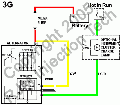
Wiring diagram of the Ford 3G alternator charging circuit showing mega fuse, battery, regulator sensing/switching, and Y/W and LG/R wires.
Part of 1987-1991 Ford Bronco Wiring Diagrams
This document is a color-coded wiring diagram for a Ford 3G alternator charging system. It shows the alternator's internal components, the stator, rectifier (diode bridge), and voltage regulator with its 'sensing and switching circuits' and field winding, and how the unit connects to the vehicle's electrical system. The alternator B+ output feeds through a MEGA FUSE (no amp rating shown) via a red wire to the battery positive terminal. Three regulator-side connections are labeled: the S (stator) terminal uses a White/Black (W/BK) wire, the A (sense) terminal uses a Yellow/White (Y/W) wire routed to the battery-side circuit, and the I (indicator) terminal uses a Light Green/Red (LG/R) wire that runs to an optional instrument cluster charge lamp (with a 510-ohm resistor in parallel) fed by a 20A 'Hot in Run' fuse. A reader can learn the correct wire colors, terminal identifications (B+, A, S, I), fusing arrangement, and the charge-lamp/resistor circuit needed when installing or troubleshooting a 3G alternator, such as during the popular 3G alternator upgrade on older Ford trucks. The diagram carries a 2005 copyright watermark but does not state a specific model year, model, or engine applicability.
Is this accurate? Sign in to help verify it.
Frequently asked questions
- How does the Ford 3G alternator connect to the battery?
- Per the diagram, the alternator B+ output runs through a MEGA FUSE on a red wire directly to the battery positive terminal.
- What wire colors are used on the 3G alternator regulator plug?
- The diagram shows W/BK (White/Black) on the stator S terminal, Y/W (Yellow/White) on the A terminal, and LG/R (Light Green/Red) on the I terminal to the charge lamp circuit.
- What resistor is used with the instrument cluster charge lamp?
- A 510-ohm resistor is shown in parallel with the optional instrument cluster charge lamp on the LG/R circuit.
- What fuse feeds the charge indicator circuit?
- A 20A fuse in a 'Hot in Run' circuit feeds the LG/R wire that goes to the charge lamp and the regulator I terminal.
- What are the internal components shown inside the 3G alternator?
- The diagram shows the stator, rectifier (diode bridge), B+ output, and the regulator containing sensing and switching circuits plus the field winding.






No comments yet.