SuperMotors SuperMotors SUPERMOTORS Search: try “orange Bronco on 35s”
Home/ Registry/ Ford/ Bronco/ 1987-1991/ “Eddie Bauer”/ Photo supermotors.net/registry/media/1069665

Speed control troubleshooting hints table 31-5 with conditions,…
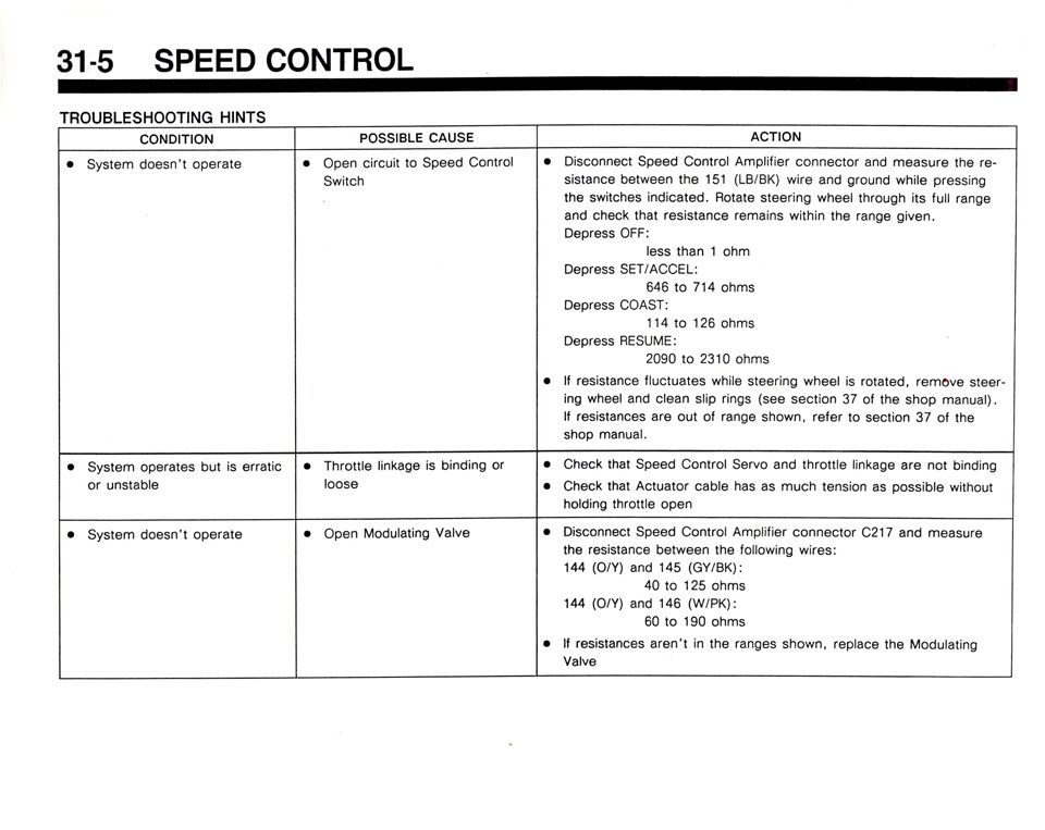
Speed control troubleshooting hints table 31-5 with conditions, causes and resistance checks
Speed control troubleshooting hints table 31-5 with conditions, causes and resistance checksOriginal file
Speed control troubleshooting hints table 31-5 with conditions, causes and resistance checks

Reference · 1987-1991 BroncoAll 53 manual pages

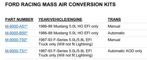
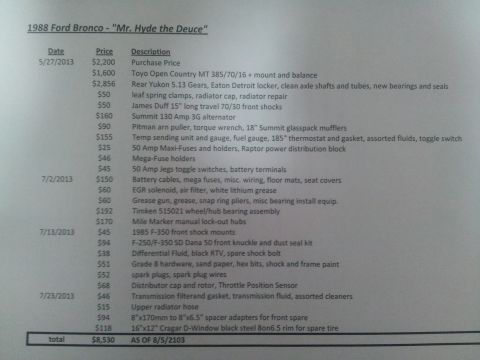
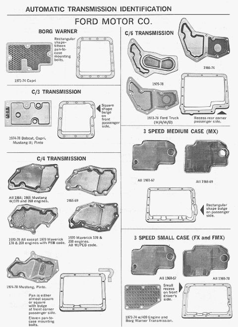
Ford 5.0L/5.8L Air Throttle Body Assembly Diagram - Canister Purge Ports & TPS Ford 5.0L/5.8L EFI Air Throttle Body Assembly Diagram - TPS & Air Bypass Valve Ford Engine/Emissions-Diagnosis 1990 Shop Manual cover Speed control troubleshooting hints table 31-5 with conditions, causes and resistance checks Instrument panel parts list with item numbers, part numbers and descriptions Ford Racing mass air conversion kits chart, M-9000-A51, B50, T50 and T51 Ford DSO and wheelbase code chart for Bronco, E-150-250-350 and F-150-250-350 and F-Super Duty 1990 Ford Bronco/F-Series Oil Pressure Gauge Specs & Sender Location 33-32-4 Ford V8 camshaft application chart for 351W and 221-302 CI engines with duration, lift and lobe separation 1988 Ford Bronco Build Cost Sheet - "Mr. Hyde the Deuce" Parts & Expense List Ford automatic transmission identification chart of oil pan shapes for C3, C4, C6, MX, FX, FMX and Borg Warner 53manual pages1987-1991 Ford Bronco More reference 1973-1974 Ford Point-Type Ignition System Circuit Diagram - Coil & DistributorWiring diagram Ford Thermactor Air Bypass Valve Cutaway Diagram - Port IdentificationSchematic Ford Canister Purge Regulator Valve (CANP 9C915) Test Procedure - Figure 11Service procedure Ford 5.8L important engine information decal with 10° BTDC timing check and ASF-32C plugSpec plate Ford 5.0L V8 PCV Valve & Hose Routing Diagram - 9A474, 6B890, 6A664Exploded parts 1990 Bronco Major Standard Equipment sheet with interior features and functional specs by trimBrochure Borgeson Steering Intermediate Shaft Measurement Diagram - U-Joint Length B & CBlueprint Ford Thermactor Combination Valve Diagram - Air Bypass/Control Ports LabeledVacuum routing 1990 Ford Bronco Fuse Panel Diagram: Fuse Positions, Amps & Circuits (11-2)Fuse chart Ford V8 Intake Manifold Bolt Tightening Sequence Diagram - Stud LocationsTorque spec

Section 31-5 speed control troubleshooting table covering switch resistance at wire 151 (LB/BK), servo linkage and modulating valve checks at connector C217.

Part of 1987-1991 Ford Bronco Manual Pages

AI caption · Photo 1738 of 1787

31 -5 SPEED CONTROL TROUBLESHOOTING HINTS couomon Possum CAUSE ACTION - Sysxem aassm overaxe . Open mmml Io Speed Canum swm - mscpnnsm Snead comm Amphsl conuecml and measure me my suslznce belween me 15v (LB/BK) wars and ground wmle pressmg ma swwchss Indlcaxau Route sxeermg whee Noug us mu Vance and check (hm resxslanco ramams Wm me Hangs awen Depvass orrv less um 1 ohm Dapvass samecn m m m ohms Depress COAST m m 23 ohms Dsprsss assume 2090 m 23m mm . u rsssusnss Hucmmes whHa sxasnng wheel .s relaxed vemeva sxaev- mg whee! m dean shp Mas (see secuan 37 0! ms shun manua} w vesvslznces are m nl mugs shown relar Io sscnon 37 a! the shop mamm - Sysmm opsvues pm s srvauc or unslame - Thymus nmge s hmdmg 0v loose Check mal Speed Comm 5st and (Name mkuqs are Ivm hmmng check Ihzl Acmzwv cable has as much lansmn as possme wuhaux npmmg moms open . Sysxam dossn'l opsraxa . Open Modmulmg ma - Discunnecl Speed Cnmrm Ampunsv cunnemov cm and measme m5 vasslunca helwsan ma comng mes m (ON) and <45 (Gwen 40 w 25 ohms 144 (GM and ma Wm: 50 w 190 ohms . u Isslslances avanl m we ranges shown. rspmce ma Madman/v9 vms

Is this accurate? Sign in to help verify it.

Comments

No comments yet.

More 1987-1991 Broncos