1990 Ford Bronco/F-Series Oil Pressure Gauge Specs & Sender Location 33-32-4
Reference · 1987-1991 BroncoAll 53 manual pages

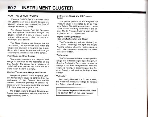
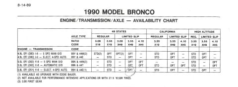
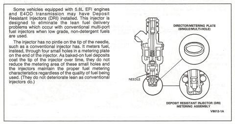
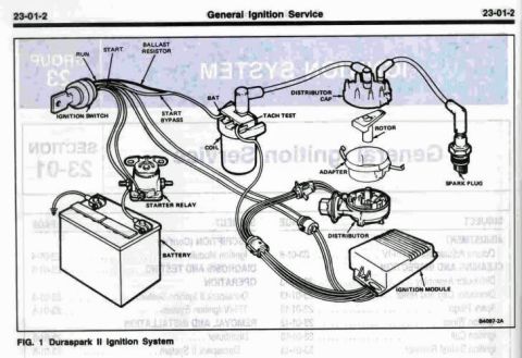








Scanned service manual page covering the oil pressure gauge with a specifications table, oil pressure sender figures and special service tool list.
Part of 1987-1991 Ford Bronco Manual Pages
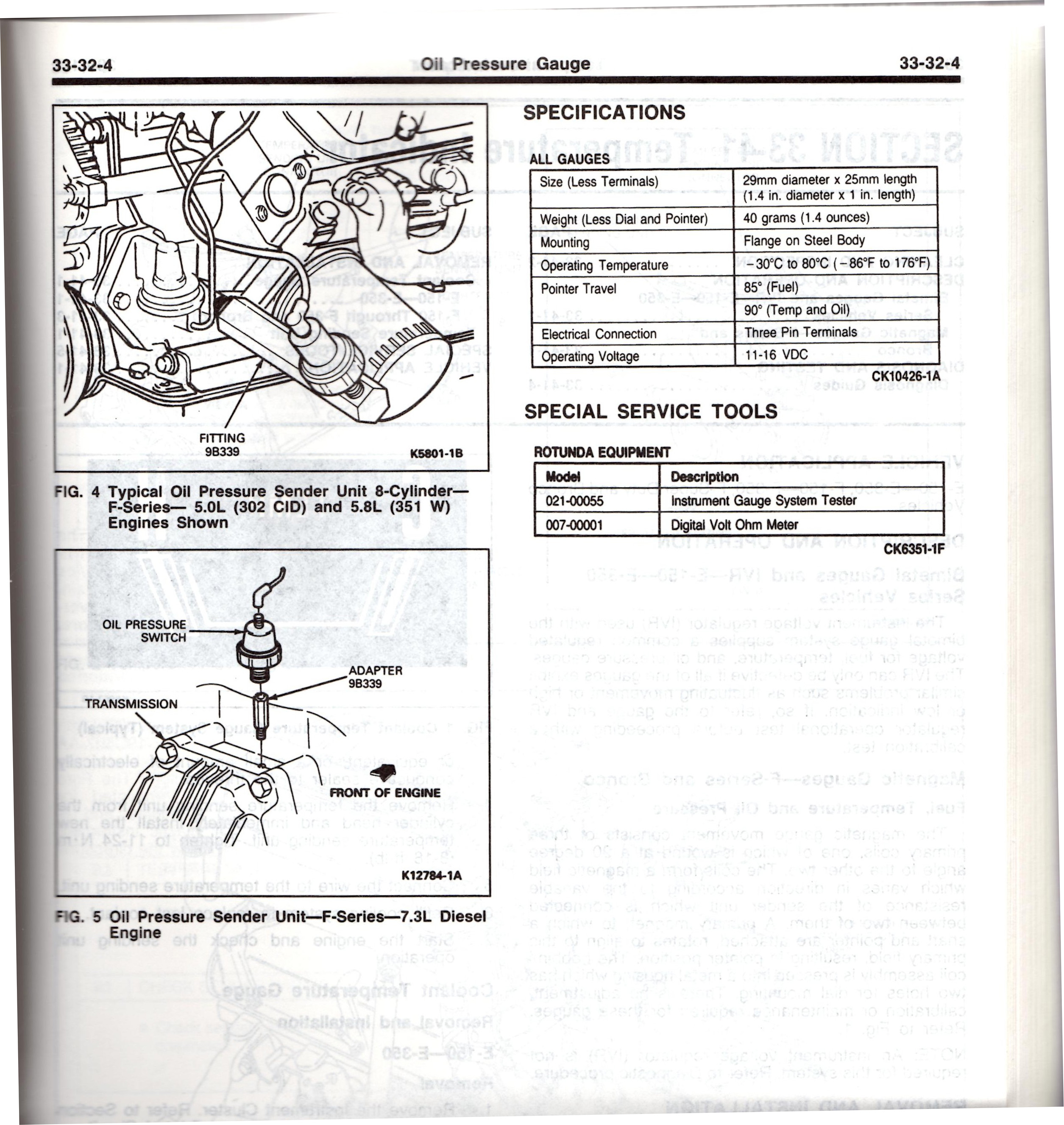
This is page 33-32-4 from a Ford factory service manual section covering the Oil Pressure Gauge. The page includes two illustrations: FIG. 4 shows a typical oil pressure sender unit location on 8-cylinder F-Series 5.0L (302 CID) and 5.8L (351 W) engines, identifying fitting 9B339; FIG. 5 shows the oil pressure sender unit on the F-Series 7.3L Diesel engine, labeling the oil pressure switch, adapter 9B339, transmission, and front-of-engine orientation. A SPECIFICATIONS table for all gauges lists: size 29mm diameter x 25mm length (1.4 in. x 1 in.), weight 40 grams (1.4 ounces) less dial and pointer, flange-on-steel-body mounting, operating temperature −30°C to 80°C, pointer travel of 85° (fuel) and 90° (temp and oil), three-pin terminal electrical connection, and 11-16 VDC operating voltage. A SPECIAL SERVICE TOOLS section lists Rotunda equipment: model 021-00055 Instrument Gauge System Tester and model 007-00001 Digital Volt Ohm Meter. Much of the right column text visible on the scan is bleed-through from the reverse page and is not legible. The page is useful for locating the oil pressure sender on gas and diesel F-Series/Bronco engines and for gauge electrical specifications.
Is this accurate? Sign in to help verify it.
Frequently asked questions
- Where is the oil pressure sender on a Ford 5.0L (302) or 5.8L (351W) V8?
- FIG. 4 shows the typical oil pressure sender unit location for 8-cylinder F-Series 5.0L (302 CID) and 5.8L (351 W) engines, mounted via fitting 9B339.
- What is the operating voltage of the Ford instrument gauges?
- The specifications table lists an operating voltage of 11-16 VDC for all gauges.
- How much pointer travel do the gauges have?
- Pointer travel is 85° for the fuel gauge and 90° for the temperature and oil gauges.
- What special tools are listed for gauge diagnosis?
- Rotunda Equipment model 021-00055 Instrument Gauge System Tester and model 007-00001 Digital Volt Ohm Meter.
- Where is the oil pressure sender on the 7.3L diesel F-Series engine?
- FIG. 5 shows the oil pressure switch mounted with adapter 9B339 near the transmission at the rear of the engine, with the front of engine indicated for orientation.






No comments yet.