Home/
Registry/
Ford/
Crown Victoria/
1998-2011/
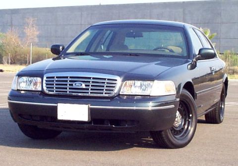
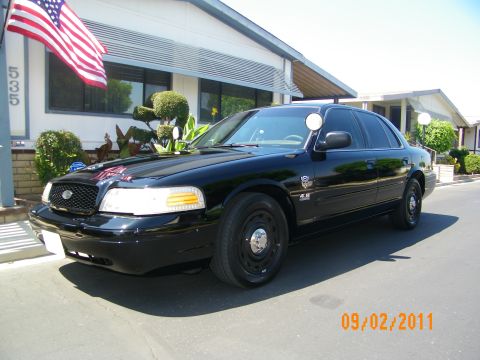
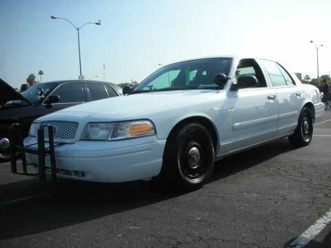
2000 Ford Crown Victoria/
Photo
supermotors.net/registry/media/1076725
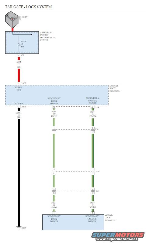
Tailgate Lock System Wiring Diagram - BCM, Fuse 14 40A, Circuits P235/P237
Reference · 1998-2011 Crown VictoriaAll 29 wiring diagrams
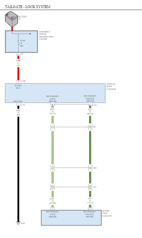

Wiring diagram of a tailgate lock system showing the body control module, fuse, and color-coded secondary lock and unlock circuits.
Part of 1998-2011 Ford Crown Victoria Wiring Diagrams
This is a single-page wiring diagram titled "TAILGATE - LOCK SYSTEM" showing the electrical circuit for a power tailgate lock. Power flows from the battery (A0) through Fuse 14 (40 A) in the Power Distribution Center, then via circuit A934 (12-gauge red wire, pin 21 of connector C6) to the Fused B(+) input (pin 3, connector C2/B) of the Body Control Module. The module is grounded through circuit Z906 (18-gauge black wire, pin 1 of connector C3/C) to ground point G107. Two output circuits leave the module: the Secondary Lock Driver on circuit P235 (18-gauge light green/tan, pin 42) and the Secondary Unlock Driver on circuit P237 (18-gauge dark green/tan, pin 41, connector C3/E). Both circuits pass through several intermediate connectors (pins 1/2, 8/7, G/H, with connector references such as D20, 1530, 1531) before reaching the tailgate lock motor, where the wire colors change to P235 18 LG/DB (lock driver, pin 1) and P237 18 VT/LG (unlock driver, pin 2). A reader can learn fuse rating, circuit numbers, wire gauges and colors, connector pin assignments, and the ground location for diagnosing tailgate lock faults.
Is this accurate? Sign in to help verify it.
Frequently asked questions
- What fuse powers the tailgate lock system in this diagram?
- Fuse 14, a 40 A fuse located in the Power Distribution Center, fed from the battery (A0).
- What circuit and wire feed power from the fuse to the Body Control Module?
- Circuit A934, a 12-gauge red (RD) wire, from pin 21 of connector C6 to pin 3 of connector C2/B (Fused B(+) input of the Body Control Module).
- What are the lock and unlock driver circuits for the tailgate lock motor?
- The Secondary Lock Driver is circuit P235, 18-gauge light green/tan (LG/TN) from BCM pin 42, becoming LG/DB at the motor. The Secondary Unlock Driver is circuit P237, 18-gauge dark green/tan (DG/TN) from BCM pin 41 (connector C3/E), becoming VT/LG at the motor.
- Where does the Body Control Module ground in this circuit?
- Through circuit Z906, an 18-gauge black (BK) wire from pin 1 of connector C3/C to ground point G107.
- Which module controls the tailgate lock motor?
- The Body Control Module, which provides the Secondary Lock Driver and Secondary Unlock Driver outputs to the tailgate lock motor.


No comments yet.