Home/
Registry/
Ford/
Crown Victoria/
1998-2011/
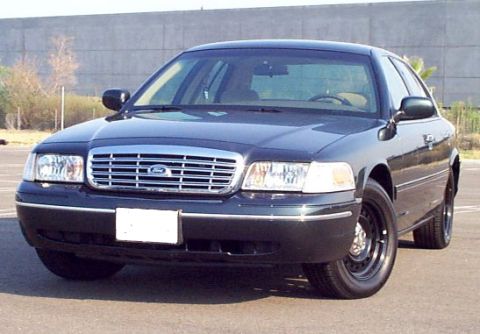
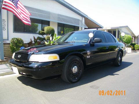
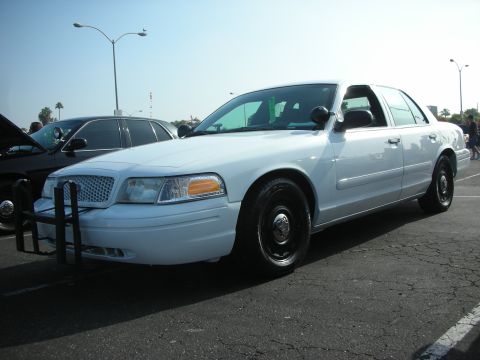
2000 Ford Crown Victoria/
Photo
supermotors.net/registry/media/1076726
Power Door Lock & Door Ajar Switch Wiring Diagram - Latch Circuits P777/P292
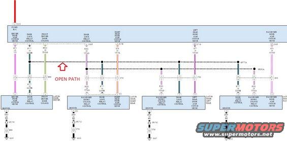
Wiring diagram of door lock relay control circuits with color-coded wires and a highlighted open-path fault.
This is a color wiring schematic for a vehicle's power door lock and door-ajar switch sensing circuits. A central module (fed FUSED B(+) at pin 1 of connector C3/C) connects to four door latch assemblies: driver (LATCH-DOOR-DRIVER), right rear, left rear, and passenger. The diagram identifies each circuit by number, gauge, and wire color: door lock relay control P777 18 LG/DB, passenger doors unlock relay control P292 18 VT/LG, front driver door unlock P910 18 TN/LG, and door ajar switch sense wires G75 18 VT (driver), G76 20 VT/YL (right rear), G77 20 VT/GY (left rear), and G74 18 VT/WT (passenger). Module connectors used include C3/C, C5/E, C6/F, and C7/G; in-line connectors I600, I650, I700, and I750 pass the circuits into each door, and splices SP777A and SP292A distribute the lock/unlock control lines. Ground circuits Z905, Z906, and Z909 (all 18 BK) run through splices SP1700, SP1702, SP1712, and SP1500 to ground points G105, G107, and G210. A red "OPEN PATH" annotation with an arrow marks a suspected break in the P777 door lock relay control bus near connector I600, apparently documenting a diagnosis of a non-working door lock circuit.
Is this accurate? Sign in to help verify it.
Frequently asked questions
- What wire is the door lock relay control circuit?
- Circuit P777, 18 gauge, light green/dark blue (LG/DB), distributed through splice SP777A to each door latch's DOOR LOCK RELAY CONTROL pin.
- What circuit unlocks the passenger doors?
- P292, 18 gauge VT/LG (violet/light green), labeled PASSENGER DOORS UNLOCK RELAY CONTROL, splitting at splice SP292A to the right rear, left rear, and passenger door latches.
- What are the door ajar switch sense wires for each door?
- Driver: G75 18 VT; right rear: G76 20 VT/YL; left rear: G77 20 VT/GY; passenger: G74 18 VT/WT.
- How are the door latches grounded?
- Driver latch: Z905 18 BK through SP1700 and connector I600 to G105. Right rear: Z909 18 BK through SP1712 and I750 to G210. Left rear: Z906 18 BK through SP1702 and I700 to G107. Passenger: Z909 18 BK through SP1500 and I650 to G210.
- What does the red 'OPEN PATH' annotation indicate?
- It marks a break (open circuit) in the P777 door lock relay control line near in-line connector I600 on the driver door circuit, added as a diagnostic note on the diagram.
Comments
More from this build





No comments yet.