Home/
Registry/
Ford/
Crown Victoria/
1998-2011/
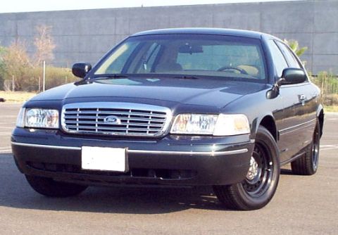
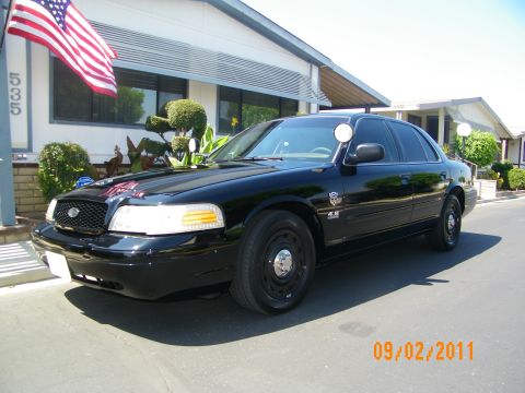
1999 Ford Crown Victoria/
Photo
supermotors.net/registry/media/523904
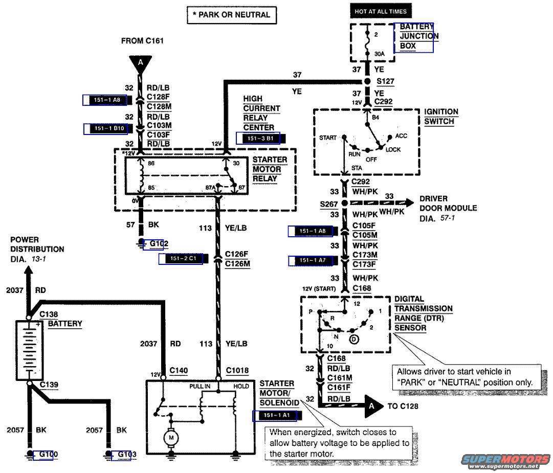
1999 Ford Crown Victoria Starting Circuit Wiring Diagram - Starter Relay & DTR
Reference · 1998-2011 Crown VictoriaAll 29 wiring diagrams
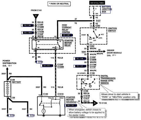
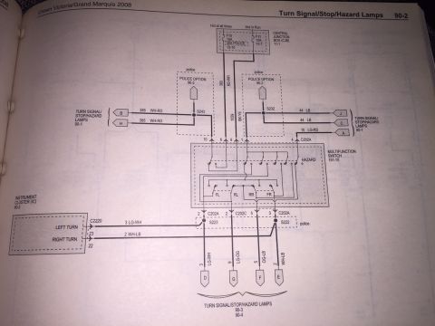
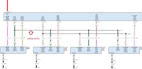
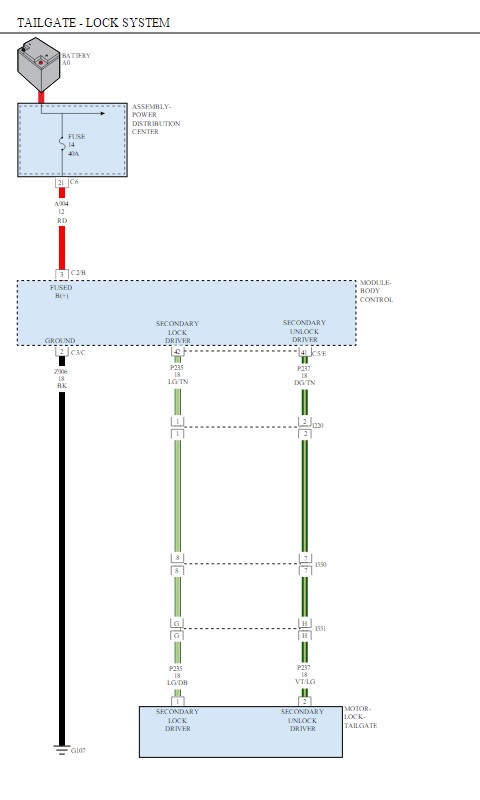
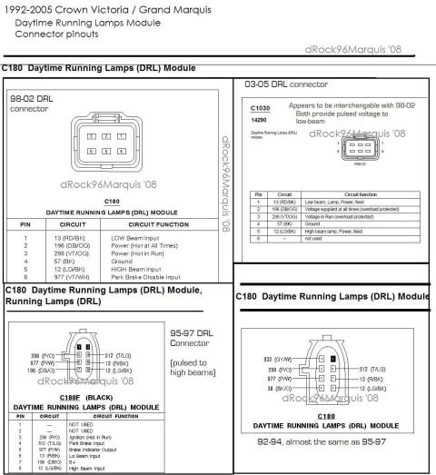

Starting-system schematic showing battery junction box, starter motor relay and solenoid, ignition switch positions, digital transmission range (DTR) sensor, and driver door module, enabling start only in PARK or NEUTRAL.
Part of 1998-2011 Ford Crown Victoria Wiring Diagrams
This document is a starting circuit wiring diagram, uploaded for a 1999 Ford Crown Victoria. It traces the starter system from the Battery Junction Box (30A fuse, position 2, hot at all times) through circuit 37 (YE) via splice S127 and connector C292 to the ignition switch (START/RUN/OFF/LOCK/ACC positions). From the ignition switch STA terminal, circuit 33 (WH/PK) runs through splice S267 (with a branch to the Driver Door Module, diagram 57-1), through connectors C105F/C105M and C173M/C173F, to the Digital Transmission Range (DTR) sensor, which permits starting only in Park or Neutral. Circuit 32 (RD/LB) then continues through C168, C161M/C161F, C128F/C128M and C103M/C103F to energize the Starter Motor Relay in the High Current Relay Center (terminals 86/85 coil, 30/87/87A contacts, grounded via circuit 57 BK at G102). Relay output circuit 113 (YE/LB) feeds the starter solenoid (pull-in and hold windings) at C1018, which applies battery voltage to the starter motor. Battery feeds are shown via circuit 2037 RD (C138/C140) with grounds 2057 BK at G100 and G103; power distribution is referenced to diagram 13-1. Grid references such as 151-1 A8, 151-1 B10, 151-3 B1, 151-2 C1, and 151-1 A1 are included for connector and component locations.
Is this accurate? Sign in to help verify it.
Frequently asked questions
- What fuse powers the starting circuit?
- A 30A fuse in position 2 of the Battery Junction Box, which is hot at all times, feeds circuit 37 (YE) to the ignition switch.
- What allows the vehicle to start only in Park or Neutral?
- The Digital Transmission Range (DTR) sensor, the diagram notes it 'Allows driver to start vehicle in PARK or NEUTRAL position only.'
- What wire feeds the starter solenoid from the starter motor relay?
- Circuit 113 YE/LB (yellow/light blue) runs from the starter motor relay through connectors C126F/C126M to C1018 at the starter motor/solenoid.
- Where is the starter motor relay located?
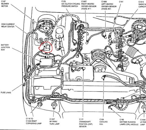
- In the High Current Relay Center (grid reference 151-3 B1), with coil terminals 86/85 and contact terminals 30, 87 and 87A; its ground is circuit 57 BK to G102.
- What wire color is the DTR sensor signal circuit from the ignition switch?
- Circuit 33 WH/PK (white/pink) carries the 12V START signal from the ignition switch through S267, C105F/C105M and C173M/C173F to C168 at the DTR sensor.

No comments yet.