Home/
Registry/
Ford/
Crown Victoria/
1998-2011/
“None Yet”/
Photo
supermotors.net/registry/media/525044
Ford Crown Victoria Fog Light Relay Wiring Diagram - Lowbeam Trigger & Override
Reference · 1998-2011 Crown VictoriaAll 29 wiring diagrams
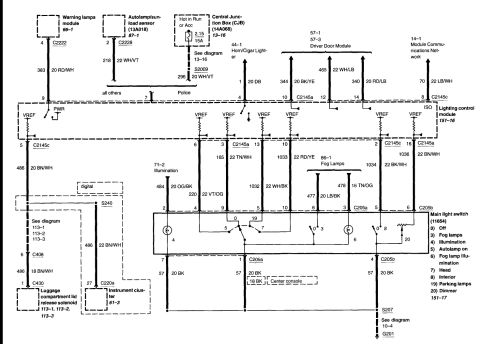
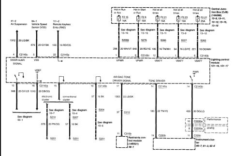
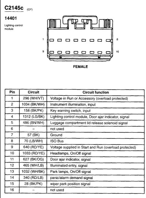
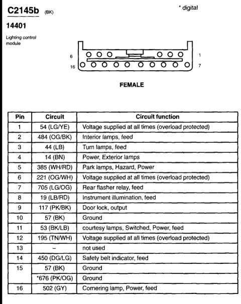

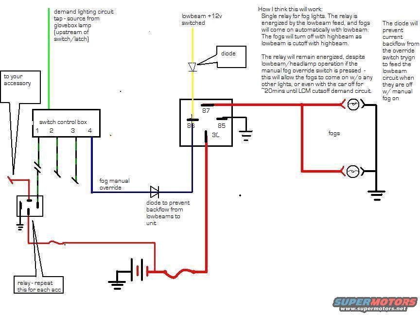
Hand-drawn color wiring diagram of a fog light relay circuit with switch, diode, ground, and explanatory notes.
Part of 1998-2011 Ford Crown Victoria Wiring Diagrams
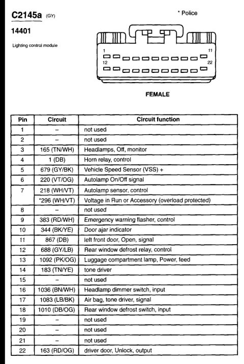
This is a hand-drawn (computer-sketched) DIY wiring diagram for adding fog lights using a single automotive relay. The design taps the demand lighting circuit from the glovebox lamp (upstream of its switch/latch) and uses a switched lowbeam +12V feed to energize the relay coil (terminals 85/86), so the fog lamps come on automatically with the low beams and turn off with high beams (since lowbeam power is cut with highbeam). A four-position switch control box provides a manual fog override, wired through a diode to prevent current backflow from the override circuit into the lowbeam circuit. With the override pressed, fogs can operate without any other lights, or even with the car off for about 20 minutes until the LCM (Lighting Control Module) cuts off the demand circuit. The relay's terminal 87 feeds the two fog lamps, which are grounded on the far side; the relay and lamps have chassis grounds shown. A note indicates the relay setup should be repeated for each accessory. The diagram uses colored wires (green demand tap, yellow lowbeam feed, blue override, red power/output, black grounds) and shows two diodes: one at the lowbeam feed and one in the override line. Useful for anyone wiring relay-controlled fog lamps tied to lowbeam operation with manual override on an LCM-equipped Ford.
Is this accurate? Sign in to help verify it.
Frequently asked questions
- How are the fog lights triggered in this wiring diagram?
- A single relay is energized by the switched lowbeam +12V feed, so the fogs come on automatically with the low beams and turn off with high beams, since lowbeam is cut off with highbeam.
- What is the purpose of the diodes in this fog light circuit?
- One diode prevents backflow from the lowbeams to the unit, and the other prevents current backflow from the manual override switch trying to feed the lowbeam circuit when the lowbeams are off but manual fog is on.
- Can the fog lights work with the car off using this setup?
- Yes. With the manual fog override switch pressed, the relay remains energized, allowing the fogs to come on without any other lights, or even with the car off for about 20 minutes until the LCM cuts off the demand circuit.
- Where does the diagram source the demand lighting circuit power?
- From a tap on the glovebox lamp, upstream of its switch/latch.
- Which relay terminals are used?
- The relay shows terminals 87, 86, 85, and what appears to be 30; terminal 87 feeds the fog lamps.

No comments yet.