1992-2005 Crown Victoria / Grand Marquis DRL Module Connector Pinouts (C180)
Reference · 1998-2011 Crown VictoriaAll 29 wiring diagrams
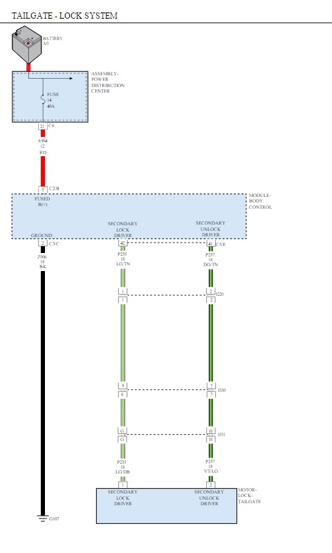
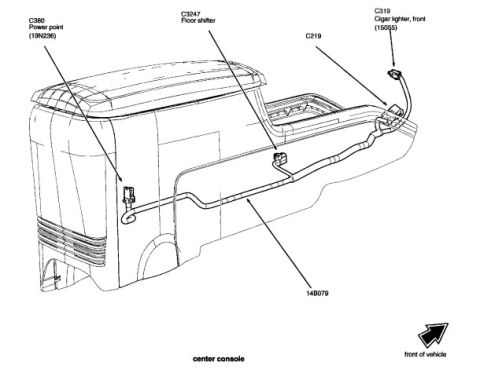
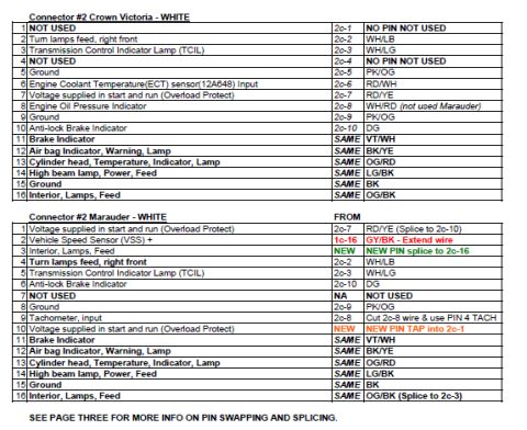
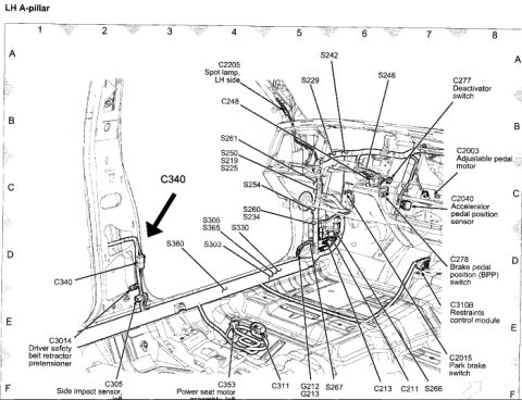
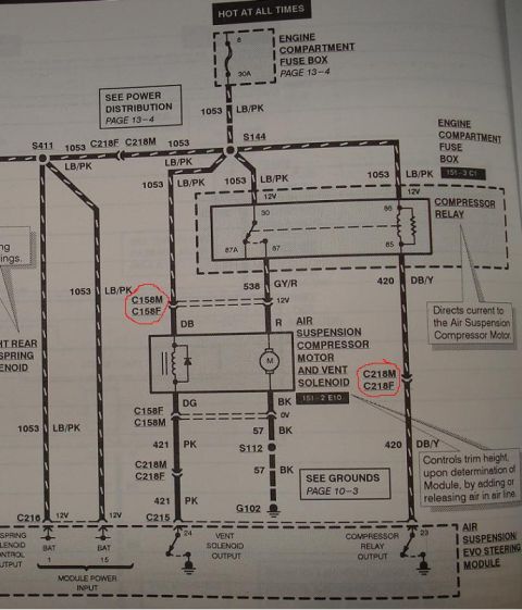


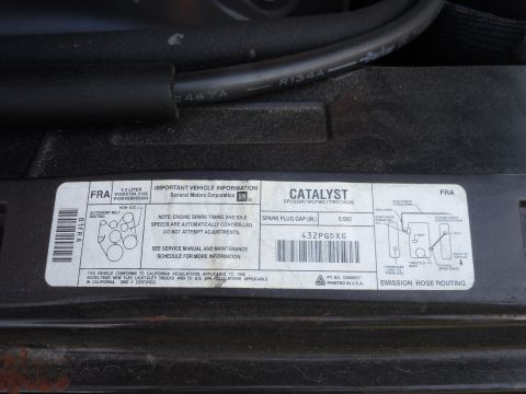
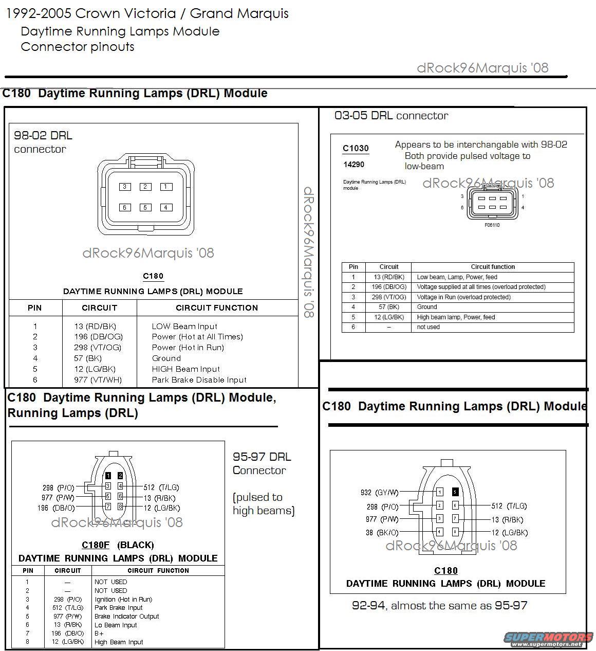
DRL module connector pinout diagrams with pin/circuit/function tables for multiple Crown Victoria model years.
Part of 1998-2011 Ford Crown Victoria Wiring Diagrams
This reference document compiles Daytime Running Lamps (DRL) module connector pinouts for 1992-2005 Ford Crown Victoria and Mercury Grand Marquis vehicles, credited to dRock96Marquis ('08). It is divided into four sections by year range. The 98-02 DRL connector (C180) is a 6-pin connector with pinout: pin 1 circuit 13 (RD/BK) low beam input, pin 2 circuit 196 (DB/OG) power hot at all times, pin 3 circuit 298 (VT/OG) power hot in run, pin 4 circuit 57 (BK) ground, pin 5 circuit 12 (LG/BK) high beam input, pin 6 circuit 977 (VT/WH) park brake disable input. The 03-05 DRL connector (C1030, 14290) has nearly identical wiring with pin 6 unused; the document notes it appears interchangeable with the 98-02 unit, both providing pulsed voltage to the low beams. The 95-97 DRL connector (C180F, black) is an 8-pin connector (pulsed to high beams) with pins 1-2 unused, and circuits 298, 512, 977, 13, 196, and 12 for ignition, park brake input, brake indicator output, low beam input, B+, and high beam input. The 92-94 C180 pinout is shown as almost identical to 95-97, adding circuits 932 (GY/W) and 38 (BK/O). Useful for DRL diagnosis, retrofit, or deletion.
Is this accurate? Sign in to help verify it.
Frequently asked questions
- What are the pinouts for the 98-02 Crown Victoria DRL module connector (C180)?
- Pin 1: 13 (RD/BK) LOW Beam Input; Pin 2: 196 (DB/OG) Power (Hot at All Times); Pin 3: 298 (VT/OG) Power (Hot in Run); Pin 4: 57 (BK) Ground; Pin 5: 12 (LG/BK) HIGH Beam Input; Pin 6: 977 (VT/WH) Park Brake Disable Input.
- Is the 2003-2005 DRL module connector interchangeable with the 1998-2002 version?
- The document states the 03-05 connector (C1030) appears to be interchangeable with 98-02; both provide pulsed voltage to the low beams. On the 03-05 version, pin 6 is not used.
- Which headlights do the 1995-97 DRL modules pulse?
- The 95-97 DRL connector (C180F, black) is noted as 'pulsed to high beams,' while the 98-02 and 03-05 versions provide pulsed voltage to the low beams.
- What is the pinout of the 95-97 DRL connector C180F?
- Pins 1 and 2 are not used; Pin 3: 298 (P/O) Ignition (Hot in Run); Pin 4: 512 (T/LG) Park Brake Input; Pin 5: 977 (P/W) Brake Indicator Output; Pin 6: 13 (R/BK) Lo Beam Input; Pin 7: 196 (DB/O) B+; Pin 8: 12 (LG/BK) High Beam Input.
- How does the 92-94 DRL connector differ from the 95-97 version?
- The document says 92-94 is 'almost the same as 95-97,' but the diagram shows pin 1 wired with circuit 932 (GY/W) and pin 4 with circuit 38 (BK/O), whereas on 95-97 pins 1 and 2 are not used.

No comments yet.