Home/
Registry/
Ford/
Crown Victoria/
1998-2011/
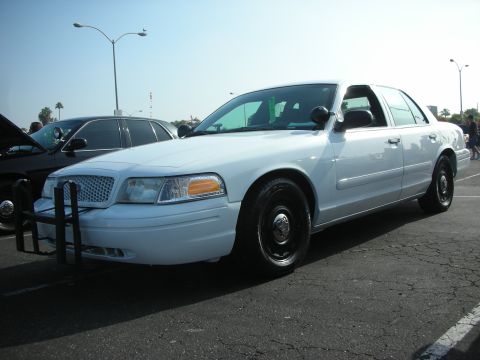
1999 Ford Crown Victoria/
Photo
supermotors.net/registry/media/521483
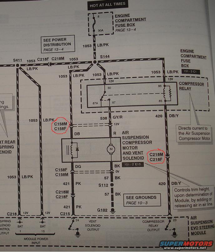
Ford Crown Victoria Air Suspension Compressor Relay Wiring Diagram - EVTM
Reference · 1998-2011 Crown VictoriaAll 29 wiring diagrams
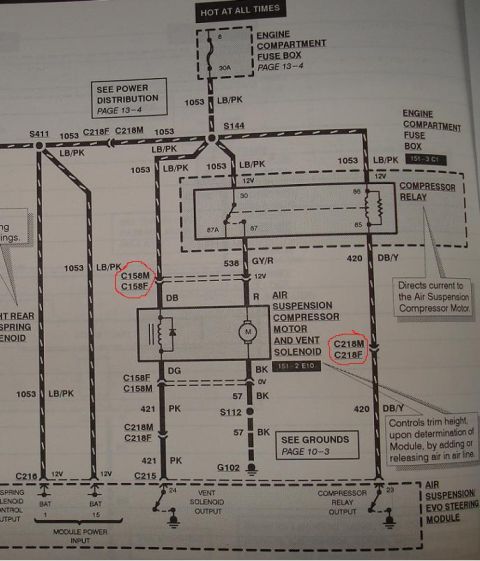
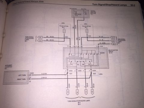
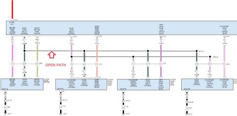
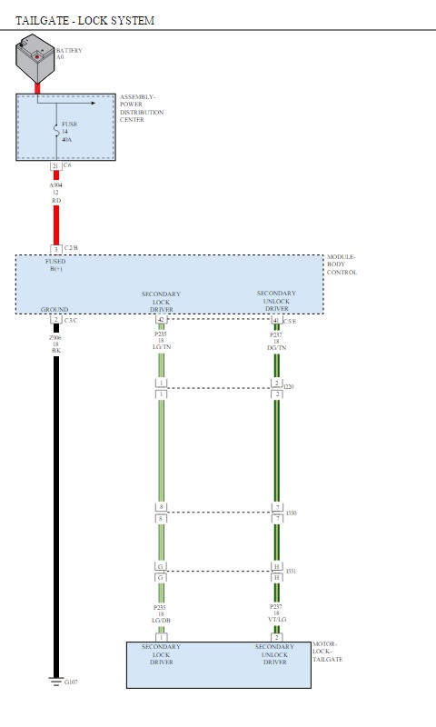
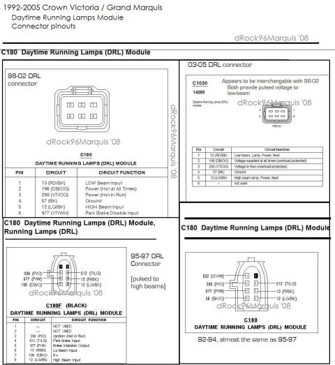

Wiring diagram for the air suspension compressor relay, motor, and vent solenoid with color-coded wires and connectors.
Part of 1998-2011 Ford Crown Victoria Wiring Diagrams
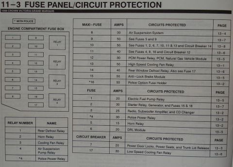
This document is a page from a Ford factory-style wiring diagram (EVTM) showing the air suspension compressor relay circuit. Power originates from a HOT AT ALL TIMES feed through a 30A fuse (position 8) in the Engine Compartment Fuse Box (referenced to Page 13-4 for power distribution). Circuit 1053 (LB/PK, light blue/pink) feeds through splices S411 and S144 and connectors C218F/C218M to the Compressor Relay in the Engine Compartment Fuse Box (grid 151-3 C1). The relay output, circuit 538 (GY/R), powers the Air Suspension Compressor Motor and Vent Solenoid (grid 151-2 E10) through connectors C158M/C158F. Ground returns via circuit 57 (BK) through splice S112 to ground G102 (See Grounds, Page 10-3). The Air Suspension/EVO Steering Module controls the system: pin 24 is the vent solenoid output (circuit 421 PK), pin 23 is the compressor relay output (circuit 420 DB/Y), and module power inputs are pins 1 and 16 (BAT). Callouts explain that the relay directs current to the compressor motor and that the module controls trim height by adding or releasing air in the air line. Connector pairs C158M/C158F and C218M/C218F are circled by the uploader, and the left rear spring solenoid circuitry is partially cut off at the page edge.
Is this accurate? Sign in to help verify it.
Frequently asked questions
- What fuse powers the air suspension compressor relay?
- A 30A fuse in position 8 of the Engine Compartment Fuse Box (power distribution shown on page 13-4), on a HOT AT ALL TIMES feed via circuit 1053 (LB/PK).
- What wire color and circuit number feed the air suspension compressor motor from the relay?
- Circuit 538, gray/red (GY/R), runs from relay pin 87 to the Air Suspension Compressor Motor and Vent Solenoid assembly through connector C158M/C158F.
- Which module pins control the compressor relay and vent solenoid?
- On the Air Suspension/EVO Steering Module, pin 24 is the vent solenoid output (circuit 421, PK) and pin 23 is the compressor relay output (circuit 420, DB/Y). Module power inputs are BAT pins 1 and 16.
- Where does the compressor motor circuit ground?
- Through circuit 57 (BK), via splice S112, to ground G102 (see Grounds, page 10-3).
- What does the compressor relay do according to the diagram?
- The callout states it directs current to the Air Suspension Compressor Motor; the module controls trim height by adding or releasing air in the air line.


No comments yet.