Home/
Registry/
Ford/
Bronco/
1992-1996/
“Eddie Bauer”/
Photo
supermotors.net/registry/media/1078650
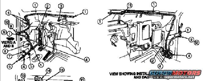
1994 Ford Bronco Cowl & Dash Wiring Harness Installation Diagram - Exploded View
Reference · 1992-1996 BroncoAll 169 exploded parts diagrams
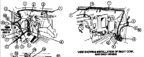












Exploded line-drawing diagram of body and cowl components labeled with numbered callouts.
Part of 1992-1996 Ford Bronco Exploded Parts Diagrams
This document is a scanned exploded-view illustration page showing the routing and installation of cowl and dash wiring harnesses in a Ford truck cab, uploaded to a 1994 Ford Bronco gallery. Two main line drawings are shown side by side. The left illustration (labeled 'VIEWS A AND B') depicts the left/driver side cowl and dash area with numbered callouts 1 through 10 pointing to wiring harness segments, retainers, and attachment points around the steering column area, dash panel, and cowl. The right illustration is captioned 'VIEW SHOWING INSTALLATION OF RIGHT COWL AND DASH WIRING' and uses callouts 1, 2, 4, 9, 11, and 12 to identify harness routing along the right cowl, dash panel, and evaporator/heater case area. A third illustration at the bottom of the page is cut off in this scan, with only callouts 13, 14, 15, and 16 visible. No parts legend, part numbers, or wire color codes are visible in the scanned portion, so the reader can learn general harness routing paths and clip locations but cannot identify individual numbered components from this scan alone.
Is this accurate? Sign in to help verify it.
Frequently asked questions
- What does this diagram show?
- It shows exploded-view illustrations of cowl and dash wiring harness installation in the cab, including a dedicated view captioned 'VIEW SHOWING INSTALLATION OF RIGHT COWL AND DASH WIRING'.
- Are the numbered callouts identified with part names or numbers?
- No. The scan shows numbered callouts (1 through 16 across the illustrations), but no legend or parts list identifying them is visible in this cropped image.
- Does the diagram cover both sides of the dash?
- Yes. The left illustration ('VIEWS A AND B') shows the driver-side cowl/dash wiring area, while the right illustration shows installation of the right cowl and dash wiring.
- Is the full page visible in this scan?
- No. A third illustration at the bottom is cut off, with only callouts 13, 14, 15, and 16 partially visible.






No comments yet.