Ford Bronco Premium Sound Radio & Wiring Connector Diagram - View B

Reference · 1992-1996 BroncoAll 169 exploded parts diagrams
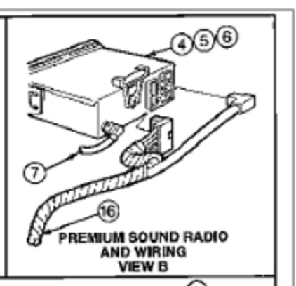
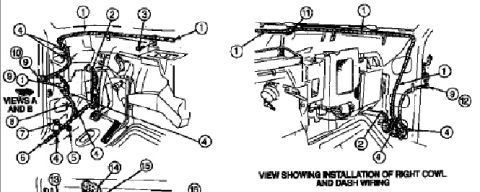












Exploded parts drawing labeled Premium Sound Radio And Wiring View B with numbered callouts for the radio unit and harness.
Part of 1992-1996 Ford Bronco Exploded Parts Diagrams
This document is a cropped exploded-view illustration labeled "Premium Sound Radio and Wiring, View B," apparently from a Ford factory service or parts manual. It depicts the rear of a radio head unit along with its associated wiring harness and connectors for a premium sound system. Five numbered callouts are visible: items 4, 5, and 6 point to components at the rear of the radio (likely rear connectors/plugs), item 7 points to a short lead or antenna/ground wire exiting the radio, and item 16 identifies the main wiring harness that runs to a large connector. No legend or parts table accompanies this crop, so the specific part names and part numbers corresponding to the callout numbers cannot be determined from this image alone. The document contains no year, model, or engine applicability statements, so it cannot be confirmed or ruled out as applying to the uploader's claimed 1994 Ford Bronco. A reader can learn the general physical arrangement of the premium sound radio connectors and harness routing, specifically which connectors plug into the back of the radio and how the harness (item 16) is dressed, but would need the accompanying legend page to identify individual components by name or part number.
Is this accurate? Sign in to help verify it.
Frequently asked questions
- What does this diagram show?
- It shows an exploded view labeled 'Premium Sound Radio and Wiring, View B', the rear of the radio unit, its connectors, and the wiring harness, with callouts 4, 5, 6, 7, and 16.
- Which callout identifies the main wiring harness?
- Callout 16 points to the wiring harness that runs from the radio area to a large connector.
- What do callouts 4, 5, and 6 point to?
- They point to components/connectors at the rear of the radio unit; the diagram does not include a legend naming them.
- Does this diagram list part numbers or wire colors?
- No. This crop shows only the illustration and callout numbers; no legend, part numbers, or wire color codes are visible.






No comments yet.