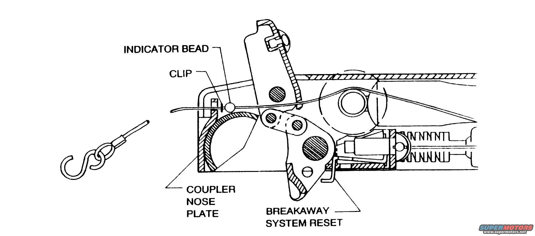
Trailer Brake Actuator Breakaway System Reset Diagram - Coupler Cutaway
Reference · 1992-1996 BroncoAll 169 exploded parts diagrams
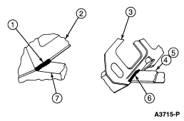
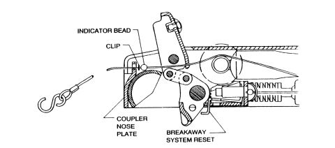












Line-art detail drawing of a trailer coupler showing indicator bead, clip, coupler nose plate and breakaway system reset components.
Part of 1992-1996 Ford Bronco Exploded Parts Diagrams
This document is a single black-and-white exploded/cutaway line drawing of a trailer coupler with an integrated breakaway (surge brake) actuator system. It was uploaded to a 1994 Ford Bronco gallery as a trailer brake actuator reference. The illustration shows the internal mechanism of the coupler in cross-section, with four labeled callouts: the INDICATOR BEAD and CLIP located on the breakaway cable where it enters the coupler body, the COUPLER NOSE PLATE at the front of the coupler housing, and the BREAKAWAY SYSTEM RESET lever inside the actuator near a spring assembly. Separately drawn at the lower left is the breakaway cable end with its S-hook and swaged cable fitting, which would attach to the tow vehicle. A reader can learn the physical location of the breakaway system reset mechanism and how the indicator bead, clip, and cable route through the coupler nose plate area. The document contains no text beyond the four callout labels, no part numbers, torque values, year/model applicability, or instructions are shown. It appears to be an excerpt from a trailer or towing equipment manual rather than a Ford vehicle-specific document, so it is trailer-side hardware rather than Bronco-specific componentry.
Is this accurate? Sign in to help verify it.
Frequently asked questions
- What parts are labeled in this trailer brake actuator diagram?
- Four items are labeled: the INDICATOR BEAD, the CLIP, the COUPLER NOSE PLATE, and the BREAKAWAY SYSTEM RESET.
- Where is the breakaway system reset located?
- Per the diagram, the breakaway system reset is a small lever/mechanism inside the coupler body, below and behind the main pivot, near the spring assembly of the actuator.
- Where are the indicator bead and clip located?
- They are shown on the breakaway cable at the top of the coupler, where the cable passes over the coupler nose plate area into the actuator.
- What is shown at the lower left of the drawing?
- The end of the breakaway cable, consisting of an S-hook attached to a swaged cable fitting with a pin/rod end.






No comments yet.