Home/
Registry/
Ford/
Bronco/
1992-1996/
“Eddie Bauer”/
Photo
supermotors.net/registry/media/1023941
1994 Ford Bronco Intake Gasket / Sealer Application Diagram (Ford Fig. A3715-P)
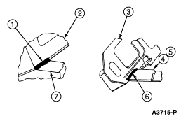
Exploded parts detail showing gasket and seal pieces with numbered callouts for installation.
Part of 1992-1996 Ford Bronco Exploded Parts Diagrams
This document is a single black-and-white line-art illustration from a Ford service reference, identified by figure number A3715-P. It contains two exploded/detail views with numbered callouts 1 through 7 but no accompanying legend or text on the page itself. The left view shows a casting (likely an end of the cylinder block or intake sealing surface) with callouts 1, 2, and 7, where a cross-hatched region indicates a sealant or gasket application area. The right view shows a bracket-shaped part with callouts 3, 4, 5, and 6, again with a cross-hatched area at its base suggesting a sealing or gasket surface. The file was uploaded to a 1994 Ford Bronco gallery under the filename "intake gasket.gif" alongside related pages covering engine and intake installation, intake gasket details, and lower intake torque sequence, so this appears to be one page of a multi-page intake manifold gasket/sealer installation procedure. Because the callout legend is not included in this scan, the reader can identify the sealant/gasket application locations visually but must consult the companion pages or service manual text to learn what each numbered item represents.
Is this accurate? Sign in to help verify it.
Frequently asked questions
- What is shown in Ford illustration A3715-P?
- Two detail views with numbered callouts 1 through 7 indicating gasket/sealant application areas (shown as cross-hatched regions) on engine components related to intake gasket installation.
- Does this diagram identify what each callout number means?
- No. The page shows only callout numbers 1-7 and the figure ID A3715-P; no legend or part descriptions are included on this scan.
- Are any part numbers or torque values listed on this page?
- No. The only alphanumeric text visible is the figure identifier A3715-P.
- How many callouts are on the diagram?
- Seven callouts: 1, 2, and 7 on the left view, and 3, 4, 5, and 6 on the right view.
Comments
More from this build







No comments yet.