Home/
Registry/
Ford/
Bronco/
1992-1996/
“Buckin Bronco”/
Photo
supermotors.net/registry/media/1110726
1996 Ford Bronco 5.8L Engine Controls Wiring Diagram: MIL & O2 Sensors (25-5)
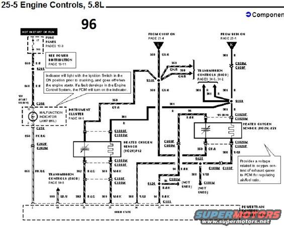
Engine controls wiring diagram for 1996 Ford Bronco 5.8L showing MIL and heated oxygen sensor circuits.
Part of 1992-1996 Ford Bronco Wiring Diagrams
This is page 25-5 of a Ford factory wiring diagram set covering Engine Controls for the 5.8L engine, marked "96" (1996). The diagram shows circuits between the fuse panel (fuse 17, 10A, hot in start or run), the Malfunction Indicator Lamp (MIL) in the instrument cluster (page 60-3), two Heated Oxygen Sensors (HO2S #12 and HO2S #21), and the Powertrain Control Module (PCM). Wire circuit numbers and colors are labeled, including 640 R/Y, 658 PK/LG, 359 GY/R, 359 GN/R, 361 R, 381 R, 94 R/BK, 392 R/LG, 389 W/BK, 388 V/LB, and 199 LB/Y. Connectors shown include C250, C251, C202F/M, C109F/M, C1069F/M, C1028F/M, C101M (not used), C185, and splices S125, S126, S136, S148, S169, S215. Notes explain that the MIL lights with the ignition ON before cranking and is turned on by the PCM if a fault develops, and that the oxygen sensors provide a voltage related to exhaust oxygen content for air/fuel ratio regulation. Cross-references point to Power Distribution page 13-11, Transmission Controls (E4OD) pages 30-3 and 30-2, and pages 25-1 and 25-4.
Is this accurate? Sign in to help verify it.
Frequently asked questions
- What fuse powers the Malfunction Indicator Lamp circuit on the 1996 5.8L?
- Fuse 17 in the fuse panel, a 10A fuse that is hot in START or RUN (fuse panel details on pages 13-3, power distribution on page 13-11).
- When does the Malfunction Indicator Lamp (MIL) come on?
- The indicator lights with the ignition switch in the ON position prior to cranking and goes off when the engine starts. If a fault develops in the Engine Control System, the PCM turns the indicator on.
- What wire colors are used for the heated oxygen sensor circuits?
- The diagram shows circuit 359 GY/R (and GN/R), 94 R/BK, 392 R/LG, 389 W/BK, and 388 V/LB feeding the HO2S #12 and HO2S #21 sensors to the PCM.
- What do the heated oxygen sensors do according to this diagram?
- They provide a voltage related to the oxygen content of exhaust gases to the PCM for regulating air/fuel ratio.
- Which connectors are used for the heated oxygen sensors?
- HO2S #12 uses connectors C1069F/C1069M and HO2S #21 uses C1028F/C1028M, both routing through C109F/C109M to the PCM at C185.
Comments
More from this build














No comments yet.