Home/
Registry/
Ford/
Bronco/
1992-1996/
“Buckin Bronco”/
Photo
supermotors.net/registry/media/1110727
1996 Ford Bronco 5.8L Wiring Diagram - Misfire Sensor & Fuel Pump Circuit 25-6
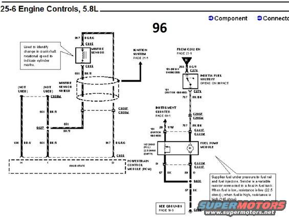
Engine controls wiring diagram for 1996 Ford Bronco 5.8L showing misfire sensor, inertia shutoff and fuel pump module circuits.
Part of 1992-1996 Ford Bronco Wiring Diagrams
This is page 25-6 of a Ford factory-style wiring diagram set, titled "Engine Controls, 5.8L," marked "96" (1996 model year), uploaded as part of a 1996 Ford Bronco documentation album. The left half shows the misfire sensor circuit: circuit 917 DG/LG and 651 BK/Y wires pass through connector C115 to the misfire sensor, which is enclosed in a shielded harness section; a note explains the sensor detects changes in crankshaft rotational speed to identify cylinder misfire. Grounds route through splice S127 and connectors C101F/C101M, C109M, and C165 to the Powertrain Control Module (PCM). The right half shows the fuel pump circuit: circuit 238 DG/Y arrives from C202 (page 25-1) through the inertia fuel shutoff switch (opens on impact), then circuit 787 PK/BK runs through C271, C205F/C205M, and C441F/C441M to the fuel pump module. The fuel level sender is a variable resistor (145 ohms full, 22.5 ohms empty) feeding the instrument cluster via circuit 29 Y/W. Grounds run via 57 BK through splice S400 to ground G100 (see grounds page 10-5). Cross-references point to the ignition system (page 21-1) and instrument cluster (page 60-1).
Is this accurate? Sign in to help verify it.
Frequently asked questions
- What does the misfire sensor do on the 1996 5.8L engine?
- Per the diagram note, it is used to identify changes in crankshaft rotational speed to indicate cylinder misfire. It connects via connector C115 with a 917 DG/LG wire and a 651 BK/Y wire inside a misfire sensor shield.
- What are the fuel level sender resistance values?
- The sender is a variable resistor: 145 ohms when the tank is full and 22.5 ohms when empty. Resistance is low when fuel is low and high when fuel is high.
- What wire feeds the fuel pump module and through which connectors?
- Circuit 787 PK/BK feeds the fuel pump module, coming from C202 (page 25-1) through the inertia fuel shutoff via connector C271, then through C205F/C205M and C441F/C441M.
- What does the inertia fuel shutoff switch do?
- It opens on impact, cutting the 12V feed (circuit 238 DG/Y, present when the relay is energized) to the fuel pump circuit.
- Where does the fuel pump module ground?
- Through wire 57 BK to splice S400 and then to ground G100 (see grounds, page 10-5).
Comments
More from this build














No comments yet.