Home/
Registry/
Ford/
Bronco/
1992-1996/
“Buckin Bronco”/
Photo
supermotors.net/registry/media/1110732
1996 Ford Bronco 5.8L Engine Controls Wiring Diagram - Fuel Injectors, IAC, PCM
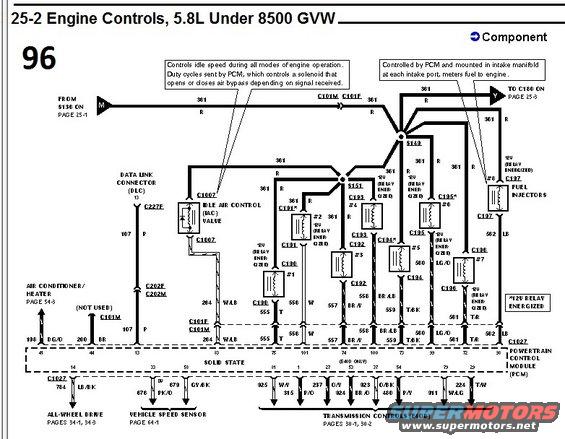
Engine controls wiring diagram for 1996 Ford Bronco 5.8L showing idle air control valve and fuel injector circuits.
Part of 1992-1996 Ford Bronco Wiring Diagrams
This is page 96 of a factory-style wiring diagram set, section "25-2 Engine Controls, 5.8L Under 8500 GVW." It shows the engine-control wiring for a 5.8L engine, centering on the Powertrain Control Module (PCM, solid state). The diagram traces the 12V relay-energized feed (circuit 361, red) from splice S136 (page 25-1) through connectors C101M/C101F and splices S149/S151 to the Idle Air Control (IAC) valve and all eight fuel injectors (connectors C190-C197), with each injector's PCM control wire identified by circuit number, color, and PCM pin (e.g., 555 T pin 75, 556 W pin 95, 557 BR/Y pin 74, 558 BR/LB pin 94, 559 T/BK pin 73, 560 LG/O pin 100, 561 T/R pin 72, 562 LB pin 98). Explanatory callouts describe the IAC valve (PCM duty-cycles a solenoid to bypass air) and fuel injectors (PCM-controlled, mounted at each intake port). Also shown: the Data Link Connector (DLC) wire 107 P to PCM pin 13, air conditioner/heater input 198 DG/O, all-wheel drive output 784 LB/BK (pages 34-1/34-3), vehicle speed sensor wires 676 P/O and 679 GY/BK (page 64-1), and E4OD transmission control circuits (pages 30-1, 30-2). Readers can use it to trace circuits, wire colors, connector IDs, and PCM pin numbers for diagnostics.
Is this accurate? Sign in to help verify it.
Frequently asked questions
- What PCM pins control the fuel injectors on the 5.8L under 8500 GVW?
- Per the diagram: injector #1 pin 75 (555), #2 pin 95 (556 W), #3 pin 74 (557 BR/Y), #4 pin 94 (558 BR/LB), #5 pin 73 (559 T/BK), #6 pin 100 (560 LG/O, E4OD only notation), #7 pin 72 (561 T/R), #8 pin 98 (562 LB).
- What powers the fuel injectors and IAC valve?
- All are fed by circuit 361 (red), marked *12V RELAY ENERGIZED, coming from splice S136 on page 25-1 through connectors C101M/C101F and splices S149/S151.
- How does the Idle Air Control (IAC) valve work according to this diagram?
- The callout states it controls idle speed during all modes of engine operation; duty cycles sent by the PCM control a solenoid that opens or closes an air bypass depending on the signal received. Its PCM wire is 264 W/LB via connectors C101F/C101M.
- What wire connects the Data Link Connector (DLC) to the PCM?
- Circuit 107, purple (P), from DLC pin 13 through connectors C227F and C202F/C202M to PCM pin 13.
- Where are the transmission control circuits continued?
- The E4OD transmission control wires (925 W/Y, 237 O/Y, 923 BR/O, 911 P/Y, 315, 924 O/V, 480 O/BK, 224 W/LG) continue on pages 30-1 and 30-2; the vehicle speed sensor is on page 64-1 and all-wheel drive on pages 34-1, 34-3.
Comments
More from this build














No comments yet.