Home/
Registry/
Hyundai/
Genesis Coupe/
2010-2016/
“Coupe”/
Photo
supermotors.net/registry/media/1116014
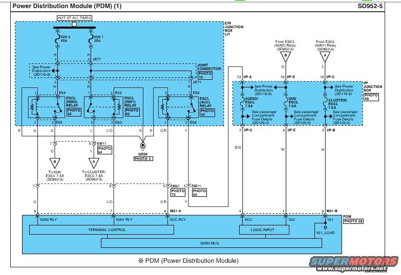
2010 Hyundai Genesis Coupe PDM Wiring Diagram SD952-5 - Power Distribution
Reference · 2010-2016 Genesis CoupeAll 79 wiring diagrams
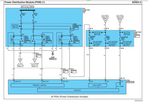
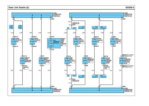








Wiring diagram of the Power Distribution Module showing ignition/accessory relays, junction box feeds and the main MCU.
Part of 2010-2016 Hyundai Genesis Coupe Wiring Diagrams
This is page SD952-5 of a Hyundai factory wiring diagram titled "Power Distribution Module (PDM) (1)," scanned from the Genesis Coupe service documentation. It shows the power distribution circuit for the PDM (used in push-button start systems). Power flows from HOT AT ALL TIMES through two fuses in the E/R Junction Box LH, IGN 2 (40A) and IGN 1 (30A), through joint connector JE71 to three relays in the same box: ESCL (IGN2) Relay (connector E54), ESCL (IGN1) Relay (E53), and ESCL (ACC) Relay (E55). Relay outputs route through connectors EM11 and EM51 and ground GE04 to the PDM connectors M51-A (pins 8 IGN2 RLY, 7 IGN1 RLY, 3 ACC RLY) and M51-B (pins 4 ACC, 1 IG2, 9 IG1). The I/P Junction Box contains three 7.5A fuses, AUDIO/ESCL, IGN/ESCL, and CLUSTER/ESCL, with references to passenger compartment fuse details on pages SD120-3, SD120-4, and SD120-5, and power distribution on SD110-8. Wire colors (R, G, L/O, O/B, B/O, W, Y, O, L, B) are labeled throughout. The PDM internal blocks shown are Terminal Control, Logic Input, IG1_LOAD, and Main MCU. Photo references (10, 42, 49, 54, 59, 72, 3) point to connector location photos in the companion manual.
Is this accurate? Sign in to help verify it.
Frequently asked questions
- What fuses feed the ESCL relays in the Genesis Coupe PDM circuit?
- Two HOT AT ALL TIMES fuses in the E/R Junction Box LH: IGN 2 (40A) and IGN 1 (30A), routed through joint connector JE71 to the ESCL (IGN2), ESCL (IGN1), and ESCL (ACC) relays.
- What fuses in the I/P Junction Box relate to the PDM/ESCL circuit?
- Three 7.5A fuses: AUDIO/ESCL, IGN/ESCL, and CLUSTER/ESCL. Passenger compartment fuse details are on pages SD120-4, SD120-5, and SD120-3 respectively.
- Which PDM connector pins carry the relay control and ignition signals?
- Connector M51-A: pin 8 IGN2 RLY (G), pin 7 IGN1 RLY (L/O), pin 3 ACC RLY (O/B). Connector M51-B: pin 4 ACC (B/O), pin 1 IG2 (W), pin 9 IG1 (G).
- Which relays are shown in the E/R Junction Box LH on this diagram?
- ESCL (IGN2) Relay at connector E54, ESCL (IGN1) Relay at E53, and ESCL (ACC) Relay at E55, all referenced to PHOTO 42.
- What internal functional blocks does the PDM contain per this diagram?
- Terminal Control, Logic Input, IG1_LOAD, and the Main MCU (PDM location shown in PHOTO 59).

No comments yet.