Home/
Registry/
Hyundai/
Genesis Coupe/
2010-2016/
“Coupe”/
Photo
supermotors.net/registry/media/1114210
2010 Hyundai Genesis Coupe AUX & USB Input Wiring Diagram - Audio/iPod Jack

Reference · 2010-2016 Genesis CoupeAll 79 wiring diagrams
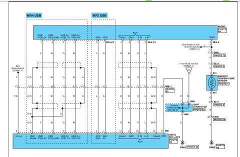
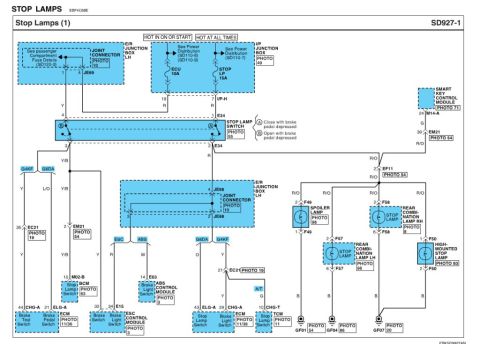
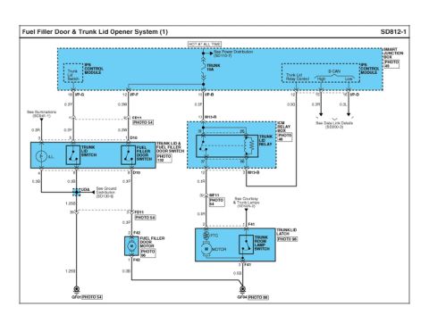
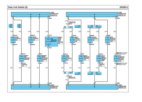
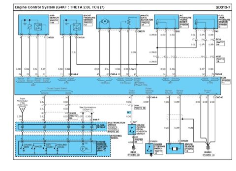








Wiring diagram of the audio USB/AUX jack and ambient temperature sensor circuits with color-coded connectors and ground points.
Part of 2010-2016 Hyundai Genesis Coupe Wiring Diagrams
This is a factory-style wiring diagram page covering the audio auxiliary (AUX) and USB/iPod input circuits, along with the ambient temperature sensor circuit, for a Hyundai Genesis Coupe (uploaded as applying to a 2010 model). The diagram is split into two variants: 'With USB' and 'W/O USB'. It shows the audio head unit connectors M03-C3 and M03-C2 with pin assignments for USB/IPOD 5V, USB/IPOD GND, USB D-/IPOD TX, USB D+/IPOD RX, GND, VDD, and AUX signals (Detect, GND, R IN, L IN), including wire colors (Y, Br, G, W, B, O, R, L, P, P/B, B/O, Br/B). Signals route through intermediate connector MM11 down to the USB & AUX jack at connector M81, with each pin and function labeled. The right side of the page traces the ambient temperature sensor circuit (TEMP.) through connectors M03-A, EM51, EE11, E91, and EM21, with grounds at GM03 and GM05 and a joint connector JM01 fed by ground distribution (SD130-2). Cross-references are given to Illuminations (SD941-1), Blower & A/C Control System (SD971-1), and Multi monitor (SD961-1) diagrams, plus photo references for connector locations (e.g., PHOTO 62, 64, 75).
Is this accurate? Sign in to help verify it.
Frequently asked questions
- What connector is used for the USB & AUX jack on the Genesis Coupe?
- Connector M81, labeled 'USB & AUX JACK' (PHOTO 75), with pins for ILL.(+), USB Shield, USB/IPOD 5V, USB/IPOD GND, USB D-/IPOD TX, USB D+/IPOD RX, AUX GND, AUX 5V, Detect, GND, R IN, L IN, and Shield.
- Which audio head unit connectors carry the USB and AUX signals?
- M03-C3 carries the USB/iPod signals (USB/IPOD 5V, USB/IPOD GND, USB D-/IPOD TX, USB D+/IPOD RX, GND, VDD) and M03-C2 carries the AUX signals (Detect, GND, R IN, L IN).
- What wire colors are used for the AUX audio lines?
- The AUX lines use O (Detect), W (GND), R (R IN), and L (L IN); near the jack the GND wire changes to Br/B.
- Where does the ambient temperature sensor circuit ground?
- The sensor's B (black) wires route through connectors E91, EE11, and EM21 to ground GM05, and via joint connector JM01 (ground distribution SD130-2) to ground GM03.
- What related diagrams does this page reference?
- It references Illuminations (SD941-1), Blower & A/C Control System (SD971-1), Multi monitor (SD961-1), and Ground Distribution (SD130-2).

No comments yet.