Home/
Registry/
Hyundai/
Genesis Coupe/
2010-2016/
“Coupe”/
Photo
supermotors.net/registry/media/1088543
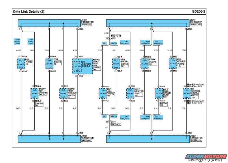
Hyundai Genesis Coupe B-CAN / M-CAN Data Link Wiring Diagram SD200-3
Reference · 2010-2016 Genesis CoupeAll 79 wiring diagrams
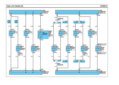








Data link wiring diagram showing joint connectors and B-CAN/M-CAN circuits to smart key, instrument cluster, navigation, and A/C control modules.
Part of 2010-2016 Hyundai Genesis Coupe Wiring Diagrams
This is page SD200-3, "Data Link Details (3)," a CAN bus wiring diagram showing two data-link networks. The left half depicts the B-CAN network connecting through joint connector JM04 (top pins 3, 1, 2, 4; bottom pins 7, 5, 6, 8, referencing PHOTO 52) to the PDM (connector M51-B, pins 11/10), BCM (M02-B, pin 5), Smart Junction Box with IPS Control Module (I/P-D, pins 15/16), Smart Key Control Module (M14-A, pins 10/11, With Button Start variants noted), and Instrument Cluster (M11, pins 34/35). The right half shows the M-CAN network through joint connector JM06 (pins 1, 2, 3 top; 5, 6, 7 bottom, PHOTO 114) to the AMP (HACO) at F03-A, AMP (JBL) at F04-A, Audio (M03-B), Multi Monitor (M30), MTS Module (M60), A/V & Navigation Head Unit (M70-B), and A/C Control Module (M06-A manual A/C or M07-A auto A/C). Branch splices route through MF31 (PHOTO 72). All CAN High and Low wires are labeled 0.3R (red, high) and 0.3L (blue, low). Configuration callouts distinguish JBL vs. HACO audio and with/without navigation builds. Photo references (e.g., PHOTO 49, 51, 59, 63, 64, 65, 90, 96, 119, 120, 135) point to connector location photos.
Is this accurate? Sign in to help verify it.
Frequently asked questions
- Which modules are on the B-CAN network in this diagram?
- The B-CAN side (through joint connector JM04, PHOTO 52) includes the PDM (M51-B), BCM (M02-B), Smart Junction Box with IPS Control Module (I/P-D), Smart Key Control Module (M14-A), and Instrument Cluster (M11).
- Which modules are on the M-CAN network?
- The M-CAN side (through joint connector JM06, PHOTO 114) includes the AMP (HACO, F03-A) or AMP (JBL, F04-A), Audio (M03-B), Multi Monitor (M30), MTS Module (M60), A/V & Navigation Head Unit (M70-B), and A/C Control Module (M06-A manual A/C or M07-A auto A/C).
- What wire sizes/colors are used for the CAN High and Low lines?
- CAN High lines are 0.3R and CAN Low lines are 0.3L throughout the diagram.
- What connector pins does the A/V & Navigation Head Unit use for M-CAN?
- Pin 1 of connector M70-B for CAN High and pin 13 of M70-B for CAN Low (connector location shown in PHOTO 119).
- How does the diagram handle different vehicle option configurations?
- Branches are labeled with condition callouts such as 'With Button Start' on the B-CAN side, and 'JBL', 'HACO', 'W/O Navigation', and 'With Navigation' on the M-CAN side, indicating which wiring applies to each build.

No comments yet.