Home/
Registry/
Hyundai/
Genesis Coupe/
2010-2016/
“Coupe”/
Photo
supermotors.net/registry/media/1101674
2010 Hyundai Genesis Coupe Stop Lamp Wiring Diagram SD927-1 - Brake Lights
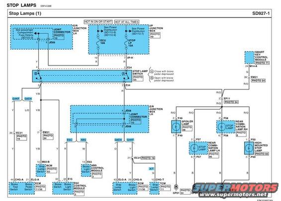
Wiring diagram of the stop lamp circuit showing the brake switch, junction boxes, lamps and color-coded wiring.
Part of 2010-2016 Hyundai Genesis Coupe Wiring Diagrams
This document is page SD927-1, titled 'Stop Lamps (1)', a factory-style wiring diagram for the stop (brake) lamp circuit. Power comes from two sources: an ECU 10A fuse (hot in ON or START) and a STOP LP 15A fuse (hot at all times), both fed through the I/P Junction Box with references to Power Distribution pages SD110-7, SD110-8, and SD110-9. The circuit runs through the Stop Lamp Switch (connector E34), which has one contact that closes and one that opens when the brake pedal is depressed. Outputs branch through joint connectors JE68/JE69 in the E/R Junction Box LH to multiple control modules: the BCM (connector M02-B pin 10), ABS Control Module (E03 pin 14), ESC Control Module (E15 pins 32/34), ECM (CHG-A/ELG-A connectors), TCM (CHG-T pin 10, A/T only), and Smart Key Control Module (M14-A pin 24). The rear lighting side (wire color R/O) feeds the spoiler lamp (F49), rear combination lamp stop lamps LH (F57) and RH (F58), and the high-mounted stop lamp (F50), all grounded via black wires to grounds GF01, GF04, and GF07. Wire colors (Y, R, Y/B, L/O, O, W, G, B, R/O) and connector pin numbers are shown throughout, with photo references for component locations.
Is this accurate? Sign in to help verify it.
Frequently asked questions
- What fuses power the stop lamp circuit on this diagram?
- Two fuses: an ECU 10A fuse (hot in ON or START) and a STOP LP 15A fuse (hot at all times), both located per the Power Distribution references SD110-7, SD110-8, and SD110-9 in the I/P Junction Box.
- How does the stop lamp switch operate?
- The stop lamp switch (connector E34, PHOTO 55) has two contacts: contact (A) closes with the brake pedal depressed and contact (B) opens with the brake pedal depressed.
- Which modules receive the brake/stop lamp switch signal?
- The BCM (M02-B pin 10), ABS Control Module (E03 pin 14), ESC Control Module (E15 pins 32 and 34), ECM (CHG-A and ELG-A connectors), TCM (CHG-T pin 10, automatic transmission only), and Smart Key Control Module (M14-A pin 24).
- What wire color feeds the rear stop lamps?
- The feed to the spoiler lamp, rear combination lamps LH/RH, and high-mounted stop lamp is R/O (red/orange), with black (B) ground wires going to grounds GF01, GF04, and GF07.
- What connectors are used for the individual stop lamps?
- Spoiler lamp uses connector F49 (pins 2 and 1), rear combination lamp LH uses F57 (pins 2 and 6), rear combination lamp RH uses F58 (pins 2 and 6), and the high-mounted stop lamp uses F50 (pins 1 and 2).
Comments
More from this build









No comments yet.