Home/
Registry/
Ford/
Bronco/
1992-1996/
“Buckin Bronco”/
Photo
supermotors.net/registry/media/1116062
Ford Bronco/F-Series Power Distribution Wiring Diagram 13-3 - Ignition Switch
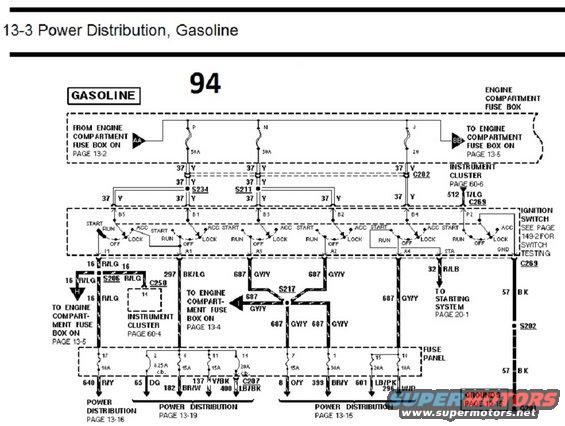
1994 gasoline power-distribution wiring diagram (page 13-3), duplicate of media 1116056, showing ignition switch positions feeding fuse box, instrument cluster and starting system with wire colors.
This document is page 13-3, 'Power Distribution, Gasoline,' from a Ford wiring diagram manual (marked '94'). It traces battery power from the engine compartment fuse box (with 50A, 50A, and 20 fusible/link positions P, N, J) through circuit 37 (yellow wires) via splices S234 and S211 to the ignition switch. The ignition switch is shown with terminals B1-B5 and P2 on the input side and I1, A1, A2, A3, A4, STA, and GND on the output side, with each wafer showing START, RUN, ACC, OFF, and LOCK positions (switch testing is referenced to page 149-2). Outputs include circuit 16 R/LG (via splice S206 to the engine compartment fuse box and to instrument cluster connector C250 pin 14), 297 BK/LG to the engine compartment fuse box (page 13-4), 687 GY/Y through splice S217 to fuse panel feeds, 32 R/LB to the starting system (page 20-1), and 57 BK ground through C269 and S202 to ground G201. The interior fuse panel section lists fuses 17 (10A), 2 (8.25A circuit breaker), 6 (15A), 11 (15A), 1 (20A circuit breaker), 7 (15A), 3 (30A), 15 (10A), and 18 (10A) with output circuits 640 R/Y, 65 DG, 182 BR/W, 137 Y/BK, 400 LB/BK, 8 O/Y, 399 BR/Y, 601 LB/PK, and 296 W/P, cross-referenced to power distribution pages 13-15, 13-16, and 13-19.
Is this accurate? Sign in to help verify it.
Frequently asked questions
- What circuit feeds the ignition switch in this power distribution diagram?
- Circuit 37 (yellow wire) feeds the ignition switch from the engine compartment fuse box through 50A links (positions P and N) and a 20 link (position J), via splices S234 and S211 and connector C202.
- What wire goes from the ignition switch to the starting system?
- Circuit 32 R/LB from the ignition switch STA terminal goes to the starting system, referenced to page 20-1.
- What fuse panel positions and ratings are shown on this page?
- Fuse 17 (10A), fuse 2 (8.25A circuit breaker), fuses 6 and 11 (15A each), fuse 1 (20A circuit breaker), fuse 7 (15A), fuse 3 (30A), fuse 15 (10A), and fuse 18 (10A).
- How is the ignition switch grounded in this diagram?
- The GND terminal connects through connector C269 on circuit 57 BK, through splice S202, to ground G201 (grounds are referenced to page 10-15).
- Which circuits are hot in RUN/ACC from the ignition switch accessory terminals?
- Circuit 687 GY/Y leaves ignition switch terminals A2, A3, and A4, passing through splice S217 to feed fuse panel positions 7, 3, 15, and 18, and also runs to the engine compartment fuse box (page 13-4).
Comments
More from this build














No comments yet.