Home/
Registry/
Ford/
Bronco/
1992-1996/
“Buckin Bronco”/
Photo
supermotors.net/registry/media/1116059
Ford Bronco Power Distribution Wiring Diagram - Fuel Pump Relay, PCM, 4WABS
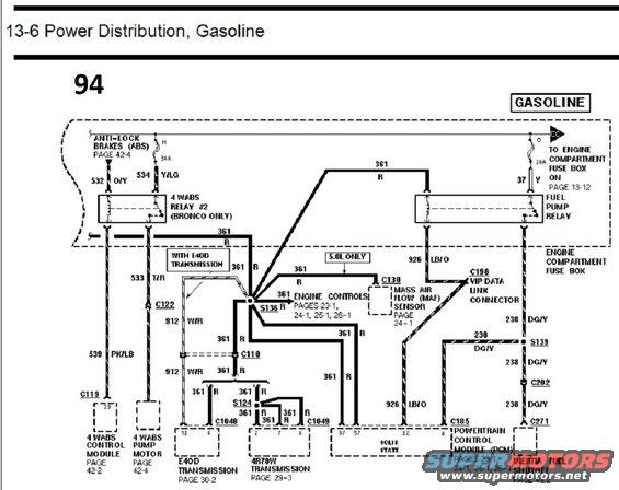
Power distribution wiring diagram showing the fuel pump relay, mass air flow sensor, ABS and transmission engine-control circuits.
This document is page 94 of a Ford wiring diagram manual, section "13-6 Power Distribution, Gasoline." It shows the power distribution circuit for gasoline engines, tracing circuit 361 (Red) from the engine compartment fuse box through a 20A fuse and the Fuel Pump Relay, and through a 30A fuse feeding the 4 WABS Relay #2 (noted as "Bronco Only") for the anti-lock brake system. Circuit 361 R distributes power via splices S136 and S124 to the Engine Controls (pages 23-1, 24-1, 25-1, 26-1), the Mass Air Flow (MAF) sensor via connector C130 (noted "5.0L only"), the E4OD transmission via C1048 (with a "With E4OD Transmission" callout and connectors C122/C110 carrying circuit 912 W/R and 533 T/R), the 4R70W transmission via C1049, and PCM connector C185 pins 57. Circuit 926 LB/O feeds the VIP Data Link Connector (C198) and PCM pin 22. Circuit 238 DG/Y runs through splice S139 and connectors C202 and C271 to the Inertia Fuel Shutoff (page 49-2). Circuits 532 O/Y, 534 Y/LG, and 539 PK/LB serve the 4 WABS control module (C119 pin 29) and pump motor. Wire colors and connector/pin numbers are labeled throughout.
Is this accurate? Sign in to help verify it.
Frequently asked questions
- What size fuse feeds the fuel pump relay in this power distribution diagram?
- A 20A fuse in the engine compartment fuse box feeds the fuel pump relay, which outputs circuit 361 R and circuit 37 Y going to the engine compartment fuse box on page 13-12.
- What wire color is circuit 361 and what does it power?
- Circuit 361 is Red (R). It powers the engine controls (pages 23-1, 24-1, 25-1, 26-1), the MAF sensor connector C130 (5.0L only), the E4OD transmission via C1048, the 4R70W transmission via C1049, and PCM connector C185 pins 57.
- Which relay is used only on the Bronco?
- The 4 WABS Relay #2 is marked "(BRONCO ONLY)" and is fed through a 30A fuse; related circuits are 532 O/Y, 534 Y/LG, 533 T/R, and 539 PK/LB to the 4 WABS control module and pump motor.
- What circuit connects to the inertia fuel shutoff switch?
- Circuit 238 DG/Y (dark green/yellow) runs through splice S139, connectors C202 and C271 to the Inertia Fuel Shutoff, covered on page 49-2.
- What circuit feeds the VIP data link connector?
- Circuit 926 LB/O (light blue/orange) feeds the VIP Data Link Connector at C198 and also goes to PCM (C185) pin 22.
Comments
More from this build














No comments yet.