Home/
Registry/
Ford/
Bronco/
1992-1996/
“Eddie Bauer”/
Photo
supermotors.net/registry/media/1120106
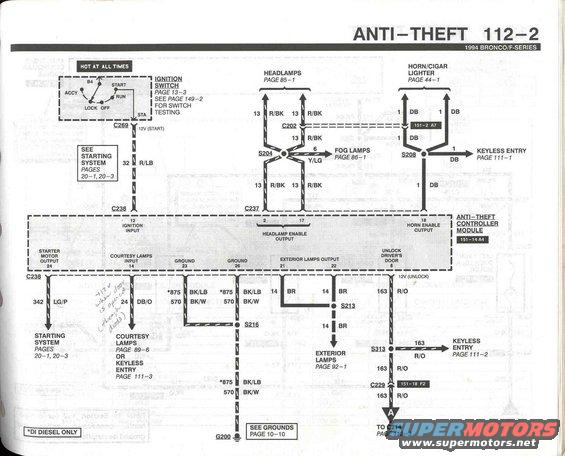
1994 Ford Bronco/F-Series Anti-Theft Wiring Diagram - EVTM Page 112-2
Reference · 1992-1996 BroncoAll 411 wiring diagrams
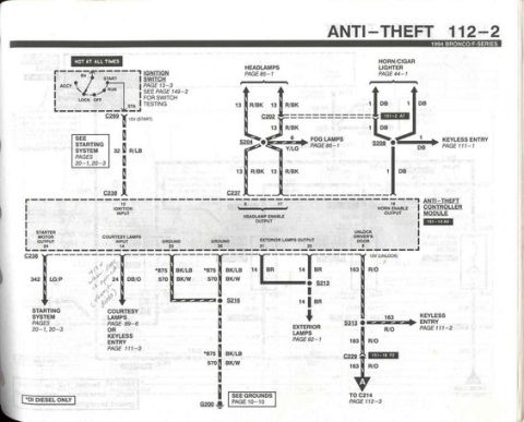














Wiring diagram for the anti-theft system showing controller module, lamps, and color-coded wires and connectors.
Part of 1992-1996 Ford Bronco Wiring Diagrams
This is page 112-2 of the 1994 Ford Bronco/F-Series Electrical and Vacuum Troubleshooting Manual (EVTM), showing the Anti-Theft system wiring diagram. It centers on the Anti-Theft Controller Module (grid location 151-14-B4) and its connections. Power comes from the hot-at-all-times circuit through the ignition switch (page 13-3), delivering 12V (START) through circuit 32 R/LB via connector C269 and C238 to the module's ignition input (pin 22). The headlamp enable output (pin 17) connects via circuit 13 R/BK through C205, S204, and C237 to the headlamps (page 85-1) and fog lamps (circuit 6 Y/LG, page 86-1). The horn enable output (pin 2) uses circuit 1 DB through S208 to the horn/cigar lighter (page 44-1) and keyless entry (page 111-1). Other module circuits include starter motor input 342 LG/P (starting system pages 20-1, 20-3), courtesy lamps input 24 DB/O, grounds 875 BK/LB and 570 BK/W to splice S216 and ground G200, exterior lamps output 14 BR via S213 (page 92-1), and unlock driver's door output 163 R/O via S313 and C229 to keyless entry (page 111-2) and continuing to C214 on page 112-3. A footnote indicates circuit 875 applies to DI diesel only.
Is this accurate? Sign in to help verify it.
Frequently asked questions
- What wire circuit feeds the anti-theft controller module's ignition input on a 1994 Bronco?
- Circuit 32 R/LB (red/light blue) carries 12V (START) from the ignition switch through connector C269 and C238 to pin 22 (ignition input) of the anti-theft controller module.
- What circuit does the anti-theft horn enable output use?
- The horn enable output (pin 2) uses circuit 1 DB (dark blue) through splice S208 to the horn/cigar lighter circuit (page 44-1) and to keyless entry (page 111-1).
- Which wire unlocks the driver's door from the anti-theft module?
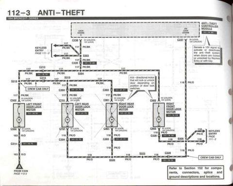
- Circuit 163 R/O (red/orange) from the module's unlock driver's door output (pin 14, 12V unlock) runs through splice S313 and connector C229 to keyless entry (page 111-2) and continues to C214 on page 112-3.
- How is the anti-theft controller module grounded?
- Grounds are on pins 23 and 20 via circuits 875 BK/LB and 570 BK/W through splice S216 to ground G200 (see grounds page 10-10). Circuit 875 is noted as DI diesel only.
- What circuit controls the headlamp flash function of the anti-theft system?
- The headlamp enable output (pin 17) uses circuit 13 R/BK through connector C205, splice S204, and C237 to the headlamps (page 85-1), with circuit 6 Y/LG branching to the fog lamps (page 86-1).






No comments yet.