Home/
Registry/
Ford/
Bronco/
1992-1996/
“Eddie Bauer”/
Photo
supermotors.net/registry/media/1120107
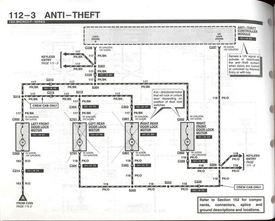
1994 Ford Bronco/F-Series Anti-Theft Wiring Diagram - EVTM Page 112-3
Reference · 1992-1996 BroncoAll 411 wiring diagrams
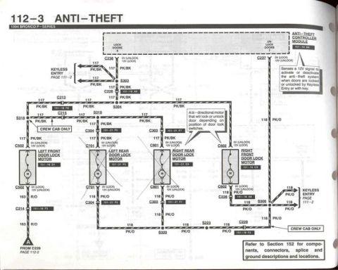














Wiring diagram of anti-theft door-lock motor circuits with controller module and color-coded wires.
Part of 1992-1996 Ford Bronco Wiring Diagrams
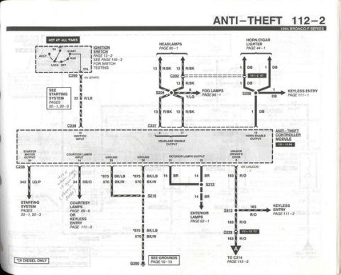
This is page 112-3 of the 1994 Ford Bronco/F-Series Electrical and Vacuum Troubleshooting Manual (EVTM), covering the Anti-Theft system wiring. The diagram shows the Anti-Theft Controller Module (grid reference 151-14 A4), which senses a 12V signal to activate or deactivate the anti-theft system when doors are locked or unlocked by Keyless Entry or with a key. Lock and unlock signals travel on circuit 117 (pink/black, PK/BK) and circuit 118 (pink/orange, PK/O), with circuit 163 (red/orange, R/O) also shown. Four bi-directional door lock motors are diagrammed: left front (151-18 D5, connector C502), left rear (151-21 F5, C701), right rear (151-21 F7, C801), and right front (151-19 C9, C602); the rear door motors are noted as "Crew Cab Only." Voltage states are labeled at each motor connector (0V/12V for lock and unlock). Splices S303, S304, S318, S319, S320, S223, and S306, plus connectors C213, C214, C215, C228, C229, C237, C239, C303, C304, and C306 are identified with grid references. Cross-references point to Keyless Entry on page 112-2 and to Section 152 for component, connector, splice, and ground descriptions and locations.
Is this accurate? Sign in to help verify it.
Frequently asked questions
- What wire colors are used for the door lock/unlock circuits on a 1994 Bronco/F-Series anti-theft system?
- Circuit 117 is pink/black (PK/BK) and circuit 118 is pink/orange (PK/O); circuit 163 is red/orange (R/O).
- What does the anti-theft controller module do on the 1994 Bronco/F-Series?
- It senses a 12V signal to activate or deactivate the anti-theft system when doors are locked or unlocked by Keyless Entry or with the key.
- How do the door lock motors work according to this diagram?
- Each is a bi-directional motor that will lock or unlock the door depending on the position of the door lock switches, with 0V/12V states shown at connectors C502, C602, C701, and C801.
- Which door lock motors apply only to Crew Cab trucks?
- The left rear (C701, 151-21 F5) and right rear (C801, 151-21 F7) door lock motors are marked 'Crew Cab Only.'
- Where can I find connector and splice locations for this circuit?
- The diagram directs you to Section 152 for component, connector, splice and ground descriptions and locations, and to page 112-2 for Keyless Entry.






No comments yet.