Home/
Registry/
Hyundai/
Genesis Coupe/
2010-2016/
“Coupe”/
Photo
supermotors.net/registry/media/1133882
2010 Hyundai Genesis Coupe OBD Data Link Connector Wiring Diagram SD200-1
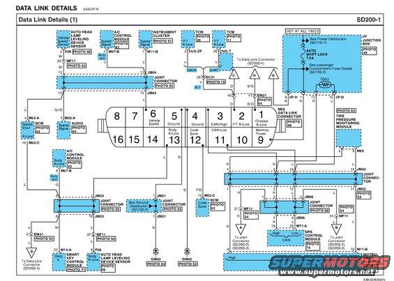
Wiring diagram of data link / CAN bus connector details (SD200-4) with multipurpose check connector pinout and color codes.
Part of 2010-2016 Hyundai Genesis Coupe Wiring Diagrams
This document is page SD200-1, "Data Link Details (1)," from a Hyundai factory electrical troubleshooting/wiring diagram set (drawing code EBKSD200AN, reference EA5C2F78). It shows the wiring of the M50 Data Link Connector (OBD-II diagnostic connector) and identifies each pin's function: pin 6 Vehicle Speed, pins 4 and 5 Ground, pin 3 CAN-High, pin 11 CAN-Low, pin 2 P/T K-Line, pin 1 Chassis K-Line/Memory Power, pin 13 Body K-Line, and pin 12 Code Save. The diagram traces these circuits to connected modules including the TCM (two variants, G6DA and G4KF engine designations), instrument cluster (M11-B), A/C control module (M07-B), audio unit (M03-A), BCM (M02-A/M02-C), smart key control module (M14-A), SRS control module (M71-A), tire pressure monitoring module (M69), vehicle speed sensor/auto headlamp leveling device sensor (F06), and joint connectors JM01, JM03, JM04, and JM06. Power comes from the I/P junction box through the AUTO SHIFT LOCK 7.5A fuse (hot at all times), with a 122Ω resistor shown in the I/P-H/I/P-D circuit. Wire colors (W, Y, L, B, R, O, B/O, Gr/O, P/B, G) and cross-references to SD110-7 power distribution, SD120-2 fuse details, SD130-2 ground distribution, and SD200-2/3/4 are included.
Is this accurate? Sign in to help verify it.
Frequently asked questions
- What are the pin functions of the data link (OBD) connector M50?
- Pin 1: Chassis K-Line/Memory Power, Pin 2: P/T K-Line, Pin 3: CAN-High, Pin 4: Ground, Pin 5: Ground, Pin 6: Vehicle Speed, Pin 11: CAN-Low, Pin 12: Code Save, Pin 13: Body K-Line. Pins 7, 8, 9, 10, 14, 15, and 16 are shown unlabeled.
- Which fuse powers the data link connector's memory power circuit?
- The diagram shows a HOT AT ALL TIMES feed through the AUTO SHIFT LOCK 7.5A fuse in the I/P Junction Box, with cross-references to Power Distribution (SD110-7) and passenger compartment fuse details (SD120-2).
- Which modules connect to the OBD connector's CAN-High and CAN-Low lines?
- The CAN High/Low lines route through joint connectors JM03 and JM06 to the SRS control module (M71-A), the instrument cluster (M11-B), and the tire pressure monitoring module (M69).
- What modules use the Body K-Line on pin 13?
- The Body K-Line connects to the A/C control module (M07-B, Auto A/C), BCM (M02-A K-Line), smart key control module (M14-A, DIAG. K), and the auto head lamp leveling device sensor (F06).
- Where does DLC pin 12 (Code Save) go?
- The Code Save circuit runs on a P/B (pink/black) wire to pin 15 of BCM connector M02-C.
Comments
More from this build









No comments yet.