Home/
Registry/
Hyundai/
Genesis Coupe/
2010-2016/
“Coupe”/
Photo
supermotors.net/registry/media/1134140
Hyundai Genesis Coupe Audio Wiring Diagram SD961-3 - JBL Amp & Speakers
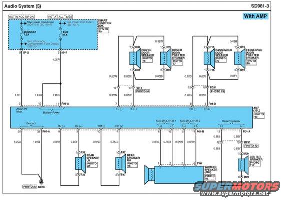
Wiring diagram of an amplified audio system showing door, tweeter, woofer, and center speaker circuits with color-coded wires and connectors.
Part of 2010-2016 Hyundai Genesis Coupe Wiring Diagrams
This is a factory-style wiring diagram page titled "Audio System (3)", sheet SD961-3, for a vehicle equipped "With AMP" (JBL amplifier system). It shows power distribution to the external amplifier: a MODULE1 7.5A fuse (hot in ACC or ON) feeding the ACC/ON input via a 0.3P wire from Smart Junction Box pin I/P-G, and an AMP 25A fuse (hot at all times) supplying battery power via 1.25R wires from I/P-F. The diagram details all speaker output circuits from the JBL amp: front left and right channels feeding the driver and passenger door speakers (D08, D18) and door tweeter speakers (D09, D19) through door pass-through connectors FD11 and FD21; rear left and right speakers via connectors F36 and F37; two subwoofer channels feeding a JBL woofer speaker through connector F40; and a center speaker fed through connectors MF31 and M09. Ground is via 1.25B wires to ground point GF08. Wire gauges and color codes (e.g., 0.85W, 0.85Br, 0.85B, 0.85Y, 0.85R, 0.85L, 0.85O, 0.85G) and connector pin numbers are labeled throughout, along with photo reference callouts (PHOTO 20-117) for connector locations. Cross-references point to power distribution sheets SD110-7/8/9 and fuse detail sheet SD120-1.
Is this accurate? Sign in to help verify it.
Frequently asked questions
- What fuses power the JBL amplifier in this audio system?
- The MODULE1 7.5A fuse (hot in ACC or ON) supplies the ACC/ON input, and the AMP 25A fuse (hot at all times) supplies battery power, both from the Smart Junction Box (see Power Distribution SD110-7/8/9 and Passenger Compartment Fuse Details SD120-1).
- What wire colors feed the front door speakers from the amp?
- Front left uses 0.85W (FL+) and 0.85Br (FL-) through connector FD11 to the driver door speaker (D08) and tweeter (D09). Front right uses 0.85Y and 0.85B through connector FD21 to the passenger door speaker (D18) and tweeter (D19).
- How is the subwoofer wired in this JBL system?
- The amp has two subwoofer channels: Sub Woofer 1 on pins 6 and 12 (0.85G/0.85O) and Sub Woofer 2 on pins 5 and 11 (0.85W/0.85Br), feeding the JBL woofer speaker through connector F40 pins 1-4.
- Where does the amplifier ground?
- The amp grounds through pins 21 and 22 (connector F04-A) using two 1.25B wires to ground point GF08 (see PHOTO 20).
- Which connectors serve the center speaker?
- The center speaker output (pins 12 and 1 of F04-A, 0.85B/0.85Y wires) passes through connector MF31 (pins 13/12) and reaches the center speaker at connector M09 (pins 1 and 2).
Comments
More from this build









No comments yet.