Home/
Registry/
Hyundai/
Genesis Coupe/
2010-2016/
“Coupe”/
Photo
supermotors.net/registry/media/1137888
2010 Hyundai Genesis Coupe Driver Power Window Wiring Diagram SD824-1
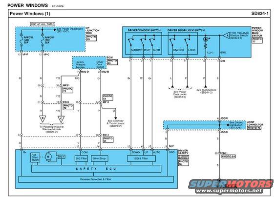
Wiring diagram of the power window system showing the driver window/door lock switches, BCM and safety window module.
Part of 2010-2016 Hyundai Genesis Coupe Wiring Diagrams
This is page SD824-1, 'Power Windows (1)', a factory-style wiring diagram covering the driver-side power window circuit. Power comes from two 25A fuses, P/WDW (LH) and P/WDW (RH), in the I/P junction box (hot at all times, see Power Distribution SD110-7). The diagram details the Power Window Main Switch, which integrates the driver window switch (M/DOWN, M/UP, AUTO contacts), the driver door lock switch (UNLOCK/LOCK), illumination (ILL+), and ground, with an input from the passenger window switch (SD824-2). It shows connector D06 and D07 pin numbers, wire colors (R, Y/B, R/O, O, Br, W, Gr, L, P, B), and intermediate connectors MF31, FD21, MF11, FD11, and joint connector JDDRI, each cross-referenced to photo numbers (49, 54, 63, 72, 76, 77). The BCM contains the safety window module and driver door switch inputs (M02-D pin 7, M02-B pin 3). The Driver Safety Window Module internal block diagram shows a Hall effect sensor, motor, relay, signal filters, short-drop function, Safety ECU, and reverse protection/filter, grounding at GF01. Cross-references point to Power Door Locks (SD813-2), Illuminations (SD941-2), Courtesy & Trunk Lamps (SD929-2), and Ground Distribution (SD130-6).
Is this accurate? Sign in to help verify it.
Frequently asked questions
- What fuses power the power windows in this diagram?
- Two 25A fuses in the I/P junction box: P/WDW (LH) 25A and P/WDW (RH) 25A, both hot at all times (see Power Distribution SD110-7).
- What functions are in the power window main switch?
- The driver window switch contacts M/DOWN, M/UP, and AUTO; the driver door lock switch with UNLOCK and LOCK positions; illumination ILL(+); ground; and an input from the passenger window switch (SD824-2).
- What components are inside the Driver Safety Window Module?
- A Hall Effect sensor, motor (M), relay (RLY), SIG Filter, Short Drop function, SIG & Filter, the Safety ECU, and Reverse Protection & Filter circuitry.
- Where does the driver safety window module ground?
- Through a black (B) wire via connector FD11 pin 39 to ground point GF01 (Photo 54), and also via joint connector JDDRI to Ground Distribution (SD130-6).
- What related diagrams does this page reference?
- Power Distribution (SD110-7), Passenger Window Switch/Safety Window Module (SD824-2), Power Door Locks (SD813-2), Illuminations (SD941-2), Courtesy & Trunk Lamps (SD929-2), and Ground Distribution (SD130-6).
Comments
More from this build









No comments yet.