Home/
Registry/
Ford/
Bronco/
1992-1996/
“Buckin Bronco”/
Photo
supermotors.net/registry/media/1137626
Ford 4.9L Engine Controls Wiring Diagram 23-5 - ECT, IAT, Knock Sensor, PCM Pins
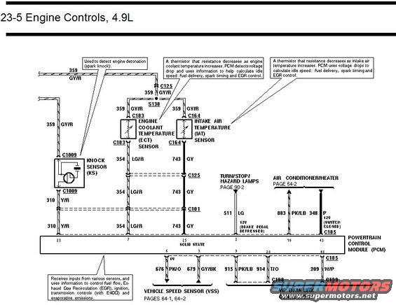
Engine controls wiring diagram for 4.9L showing knock sensor, engine coolant temperature, intake air temperature and vehicle speed sensor circuits.
This is page 23-5 of a Ford factory-style wiring diagram titled "Engine Controls, 4.9L," covering sensor circuits connected to the Powertrain Control Module (PCM). It shows the Knock Sensor (KS) at connector C1009 with circuit 310 Y/R to PCM pin 23, the Engine Coolant Temperature (ECT) sensor at connector C183 with circuit 354 LG/R to PCM pin 7, and the Intake Air Temperature (IAT) sensor at connector C164 with circuit 743 GY to PCM pin 25. Sensor signal return circuit 359 GY/R runs through splice S138 and connector C125. Inputs also include the Turn/Stop/Hazard Lamps circuit 511 LG (12V with brake pedal depressed, page 90-2) to PCM pin 2, and Air Conditioner/Heater circuits 883 PK/LB (pin 10) and 348 P (12V switch closed, pin 43, via C185) from page 54-2. Outputs/interfaces at the bottom show the Vehicle Speed Sensor (VSS, pages 64-1/64-2) on circuits 676 PK/O (pin 6) and 679 GY/BK (pin 3), plus VIP Data Link Connectors on circuits 915 PK/LB (pin 9), 914 T/O (pin 28) via C198, and 209 W/P (pin 48) via C185/C199. Callout notes explain each sensor's function: knock detection, thermistor behavior for ECT/IAT, and the PCM's control of fuel, EGR, ignition, E4OD transmission, and evaporative emissions.
Is this accurate? Sign in to help verify it.
Frequently asked questions
- What PCM pin does the knock sensor connect to on the 4.9L?
- The Knock Sensor (KS) connects through connector C1009 on circuit 310 Y/R to PCM pin 23.
- What wire color and circuit is the ECT sensor signal on the 4.9L?
- The Engine Coolant Temperature (ECT) sensor at connector C183 uses circuit 354 LG/R (light green/red), running through C125 and C101 to PCM pin 7.
- What circuit does the IAT sensor use?
- The Intake Air Temperature (IAT) sensor at connector C164 uses circuit 743 GY (gray) to PCM pin 25, with signal return 359 GY/R shared through splice S138.
- Which PCM pins connect to the Vehicle Speed Sensor (VSS)?
- The VSS connects on circuit 676 PK/O to PCM pin 6 and circuit 679 GY/BK to PCM pin 3; details are on pages 64-1 and 64-2.
- What circuits go to the VIP data link connectors?
- Circuits 915 PK/LB (PCM pin 9) and 914 T/O (PCM pin 28) via connector C198, and 209 W/P (PCM pin 48) via C185 to C199.
Comments
More from this build














No comments yet.