Home/
Registry/
Ford/
Bronco/
1992-1996/
“Buckin Bronco”/
Photo
supermotors.net/registry/media/1137624
1996 Ford Bronco 4.9L Engine Controls Wiring Diagram - Fuel Injectors & HO2S
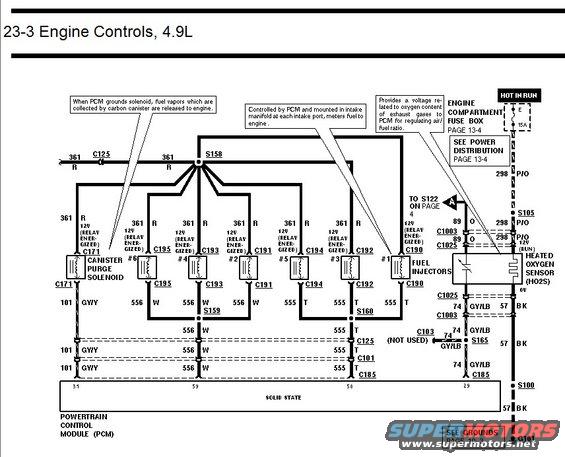
Engine controls wiring diagram for 4.9L showing canister purge solenoid, fuel injectors and heated oxygen sensor circuits.
This document is page 23-3 of a Ford wiring diagram set, covering the Engine Controls circuit for the 4.9L inline-six engine. It shows the fuel injector and canister purge solenoid wiring from the engine compartment fuse box (Hot in Run, fuse E, 15A, page 13-4) through splice S158 to all six fuel injectors (#1-#6) via connectors C190 through C195, each fed 12V (relay energized) on circuit 361 (Red). Injector return wiring uses circuits 556 (White) and 555 (Tan), routing through splices S159 and S160 and connectors C125, C101, and C185 back to the solid-state Powertrain Control Module (PCM). The canister purge solenoid is controlled via circuit 101 (GY/Y) at connector C171; a callout explains that when the PCM grounds the solenoid, fuel vapors collected by the carbon canister are released to the engine. The right side shows the Heated Oxygen Sensor (HO2S) wiring: 298 P/O 12V run feed via S105, signal circuit 89 (Orange) through C1003/C1025, and ground circuit 74 GY/LB and 57 BK through S165, S100 to ground G101 (see grounds page 10-3). C103 is marked not used. Readers can trace injector, purge solenoid, and O2 sensor circuits, wire colors, connector numbers, and splice points.
Is this accurate? Sign in to help verify it.
Frequently asked questions
- What powers the fuel injectors on the 4.9L engine?
- A 15A fuse (position E, Hot in Run) in the engine compartment fuse box feeds circuit 361 (Red), which supplies 12V (relay energized) through splice S158 to all six injectors via connectors C190-C195.
- What wire colors do the 4.9L injector control circuits use?
- Injectors #2, #4, #6 return on circuit 556 White (splice S159), and injectors #1, #3, #5 return on circuit 555 Tan (splice S160), routing through connectors C125, C101 and C185 to the PCM.
- How is the canister purge solenoid controlled?
- The PCM grounds the solenoid through circuit 101 GY/Y at connector C171; when grounded, fuel vapors collected by the carbon canister are released to the engine.
- What does the heated oxygen sensor (HO2S) do per this diagram?
- It provides a voltage related to the oxygen content of exhaust gases to the PCM for regulating the air/fuel ratio. Its heater is fed 12V (run) on circuit 298 P/O, signal is circuit 89 Orange, and grounds run on 74 GY/LB and 57 BK to G101.
- Which pages cover power distribution and grounds referenced by this diagram?
- Power distribution and the engine compartment fuse box are on page 13-4, and grounds are on page 10-3.
Comments
More from this build














No comments yet.