Home/
Registry/
Hyundai/
Genesis Coupe/
2010-2016/
“Coupe”/
Photo
supermotors.net/registry/media/1147636
Hyundai 2.0L CVVT Timing Chain Installation Procedure & Torque Specs (EM-28)
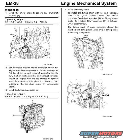
Timing chain installation procedure showing crankshaft sprocket alignment, chain guide and tightening torques.
Part of 2010-2016 Hyundai Genesis Coupe Service Procedures
This is page EM-28 from an Engine Mechanical System service manual section covering timing chain installation. The page presents a four-step installation procedure with supporting illustrations. Step 1 covers installing the timing chain oil jet and crankshaft sprocket, with a tightening torque of 7.8-9.8 N.m (0.8-1.0 kgf.m, 5.8-7.2 lb-ft). Step 2 explains setting the crankshaft key aligned with the main bearing cap mating surface and positioning the intake and exhaust camshaft assemblies so their TDC marks align with the top surface of the cylinder head, placing the No.1 piston at top dead center on the compression stroke. Step 3 covers installing the timing chain guide with a torque of 9.8-11.8 N.m (1.0-1.2 kgf.m, 7.2-8.7 lb-ft). Step 4 describes installing the timing chain with no slack, following the routing order: crankshaft sprocket, timing chain guide, intake CVVT assembly, then exhaust CVVT assembly, and matching each sprocket's timing mark with the color links on the chain. Four illustrations (SBKEM9142D, SBKEM9127D, SBKEM9103L, SBKEM9104L) show component locations and timing mark positions. The engine uses CVVT (continuously variable valve timing) on both cams. Uploaded as part of a multi-page set for a 2.0L engine timing chain install.
Is this accurate? Sign in to help verify it.
Frequently asked questions
- What is the tightening torque for the timing chain oil jet and crankshaft sprocket?
- 7.8 ~ 9.8 N.m (0.8 ~ 1.0 kgf.m, 5.8 ~ 7.2 lb-ft).
- What is the torque spec for the timing chain guide?
- 9.8 ~ 11.8 N.m (1.0 ~ 1.2 kgf.m, 7.2 ~ 8.7 lb-ft).
- In what order should the timing chain be routed during installation?
- To install the chain with no slack between each shaft (cam, crank): Crankshaft sprocket (A) -> Timing chain guide (B) -> Intake CVVT assembly (C) -> Exhaust CVVT assembly (D).
- How do you align the timing marks when installing the chain?
- The timing mark of each sprocket should be matched with the timing mark (color link) of the timing chain when installing the chain. The crankshaft key must be aligned with the mating surface of the main bearing cap, camshaft TDC marks aligned with the top surface of the cylinder head, and the No.1 piston at top dead center on the compression stroke.
- How should the crankshaft and camshafts be positioned before installing the timing chain?
- Set the crankshaft so its key is aligned with the mating surface of the main bearing cap, and position the intake and exhaust camshaft assemblies so the TDC marks of the intake and exhaust sprockets align with the top surface of the cylinder head, placing the No.1 piston at top dead center on the compression stroke.
Comments
More from this build









No comments yet.