1978 Ford Bronco Hand-Drawn Vacuum Routing Diagram - Engage/Disengage Valves
Reference · 1978-1979 BroncoAll 16 vacuum routing diagrams

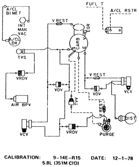
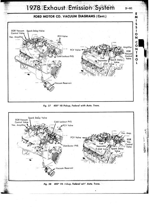
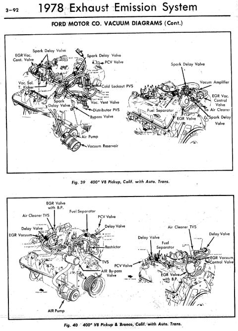
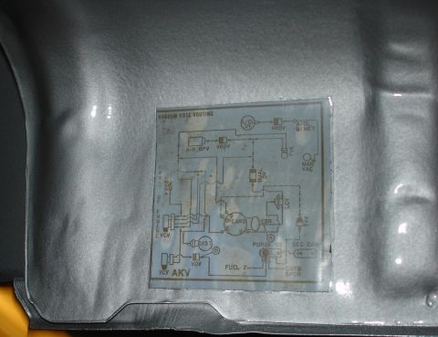

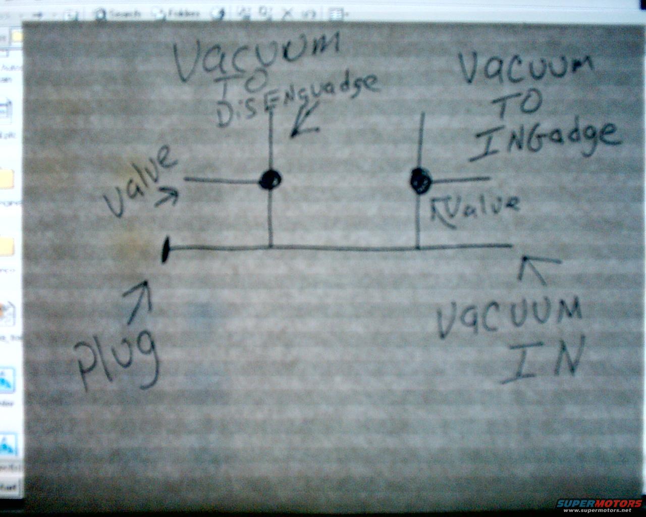
Hand-drawn vacuum routing diagram showing vacuum in, plug, and valves routed to engage and disengage functions.
Part of 1978-1979 Ford Bronco Vacuum Routing Diagrams
This document is a photograph of a simple hand-drawn vacuum routing sketch, uploaded to the gallery of a 1978 Ford Bronco. The drawing shows a single vacuum supply line with a source labeled "Vacuum IN" on the right side and a "Plug" capping the opposite (left) end of the line. Two tee branches come off this supply line, each passing through a component marked "Valve" (drawn as a filled dot). One branch is labeled "Vacuum TO Disenguadge" (i.e., vacuum to disengage) and the other "Vacuum TO INGadge" (i.e., vacuum to engage). The sketch appears intended to show how vacuum is routed to engage and disengage a vacuum-operated device, most likely front axle locking hubs or a transfer case/4WD actuator on this era of Bronco, using two valves teed off a common vacuum source, with the unused end of the line plugged. There are no part numbers, dates, torque values, or vehicle-specific identifiers visible; the drawing was photographed off a computer monitor, with parts of a Windows file-browser toolbar visible around the edges.
Is this accurate? Sign in to help verify it.
Frequently asked questions
- What does this vacuum diagram show?
- It shows a single vacuum supply line ("Vacuum IN") with two tee branches, each with a valve: one branch routes "Vacuum TO Disenguadge" (disengage) and the other routes "Vacuum TO INGadge" (engage). The opposite end of the supply line is capped with a "Plug".
- Where does the vacuum source connect in this diagram?
- The vacuum source enters at the right end of the horizontal line, labeled "Vacuum IN".
- What happens to the unused end of the vacuum line?
- The left end of the supply line is sealed with a "Plug", as labeled in the sketch.
- How many valves are shown and what do they control?
- Two valves are shown, drawn as filled dots at the tee junctions. One valve controls the line supplying vacuum to disengage, and the other controls the line supplying vacuum to engage.






No comments yet.