Spring Loaded King Pin Assembly Diagram - Front Axle Load Path Illustration
Reference · 1986-1995 SamuraiAll 18 schematics


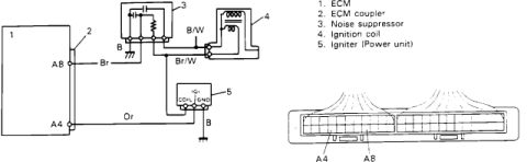
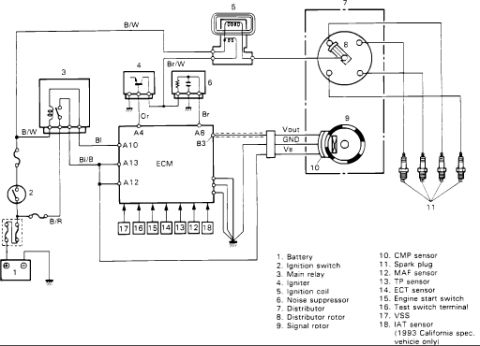
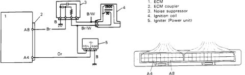

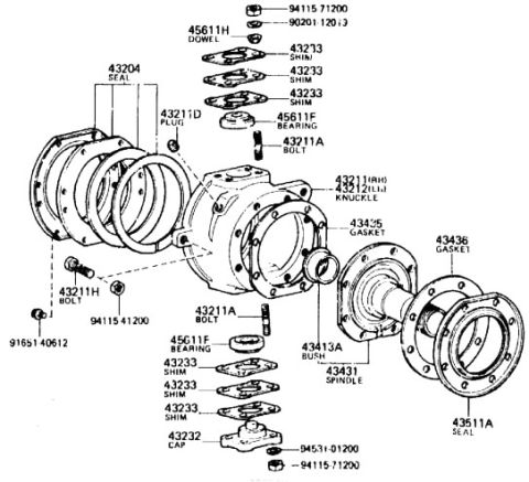
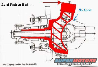
Schematic cross-section of a spring-loaded king pin assembly showing the load path highlighted in red versus the no-load area.
Part of 1986-1995 Suzuki Samurai Schematics
This document is an annotated technical cutaway illustration captioned "FIG. 2 Spring Loaded King Pin Assembly." It shows a cross-section of a front axle steering knuckle and hub assembly featuring a spring-loaded king pin design. A community member has added colored annotations to the original line drawing: the note "Load Path in Red ----" with red shading traced through the illustration indicates the structural path through which load is carried, from the upper king pin area down through the knuckle, around the axle shaft/spindle area, and through the lower knuckle region. A blue arrow labeled "No Load" points to the upper spring-loaded king pin cap area, indicating that this spring-loaded portion does not carry the vehicle load. The drawing shows the axle housing, axle shaft with universal joint, spindle, wheel hub with studs, and the upper and lower king pin areas, though none of these components are individually labeled with text. A reader can learn from this figure how load is distributed in a spring-loaded king pin front axle assembly and that the spring-loaded upper king pin itself is not a load-bearing element. No part numbers, torque specifications, years, makes, or models appear in the document.
Is this accurate? Sign in to help verify it.
Frequently asked questions
- What does this diagram show?
- It is a cutaway illustration captioned "FIG. 2 Spring Loaded King Pin Assembly," showing a cross-section of a front axle knuckle, hub, and king pin assembly.
- What do the red markings indicate?
- Per the annotation "Load Path in Red ----," the red shading traces the structural load path through the knuckle and axle assembly.
- Does the spring-loaded upper king pin carry load?
- No. A blue arrow labeled "No Load" points to the upper spring-loaded king pin area, indicating that part does not carry load.
- Are there any part numbers or torque specs in this document?
- No. The document contains only the figure caption and the two annotation labels; no part numbers, torque values, or specifications are shown.

No comments yet.