Homemade Track System Design Sketch - 1987 Suzuki Samurai Track Conversion

Reference · 1986-1995 SamuraiAll 18 schematics



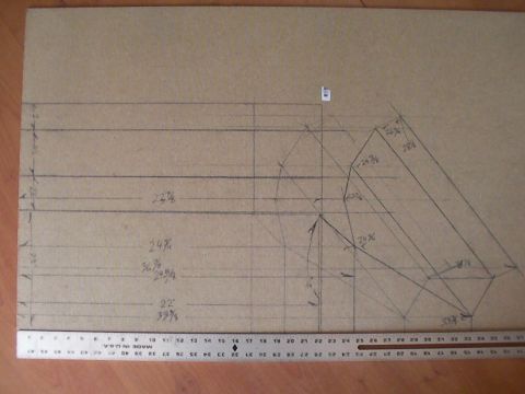
Hand-drawn conceptual schematic of a vehicle frame and wheels with a raised vertical linkage arm.
Part of 1986-1995 Suzuki Samurai Schematics
This document is a simple, untitled, hand-drawn schematic sketch (apparently made in a basic paint program) showing a conceptual design for a track system, presumably intended for conversion of a wheeled vehicle to tracks. The drawing depicts a side profile of a track unit: a green outline traces the overall belt/track shape, with a row of five or six small road wheels (drawn as blue-outlined circles) along the bottom run, a larger drive or idler wheel at the right end (black outline with green inner detail and brown belt lines), and a tall vertical arm outlined in magenta rising from the center of the assembly to a large upper wheel, likely representing the mounting arm or attachment point to the vehicle's axle/hub. Blue lines indicate the internal frame or linkage structure connecting the wheels. The document contains no text, dimensions, part numbers, or annotations, so a reader can learn only the general geometry and layout concept of the proposed track unit. Based on companion files in the same album (e.g., 'tatou-track-system.jpg', 'trackparts.JPG'), it appears to be one page of a homemade track-system design set filed under a 1987 Suzuki Samurai.
Is this accurate? Sign in to help verify it.
Frequently asked questions
- What does this schematic show?
- A side-profile sketch of a track unit design: multiple small road wheels along the bottom, a larger wheel at the right end, a belt/track outline, and a tall central arm rising to an upper wheel or hub mount.
- Does the drawing include any dimensions or part numbers?
- No. The sketch contains no text, measurements, part numbers, or labels of any kind, only colored line drawings.
- How many road wheels are shown on the bottom of the track unit?
- Roughly five to six small circles (road wheels/bogies) are drawn along the bottom run of the track.
- What do the different line colors appear to represent?
- Green outlines the overall track/belt profile, blue shows the internal frame/linkage and wheels, magenta outlines the vertical mounting arm, brown appears to trace belt/track runs at the right side, and black outlines the larger wheels.
No comments yet.