Piston Movement Concept Schematic (Unlabeled Diagram) - 1987 Suzuki Samurai Gallery
Reference · 1986-1995 SamuraiAll 18 schematics



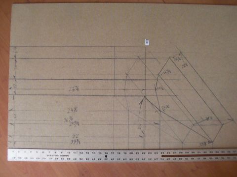
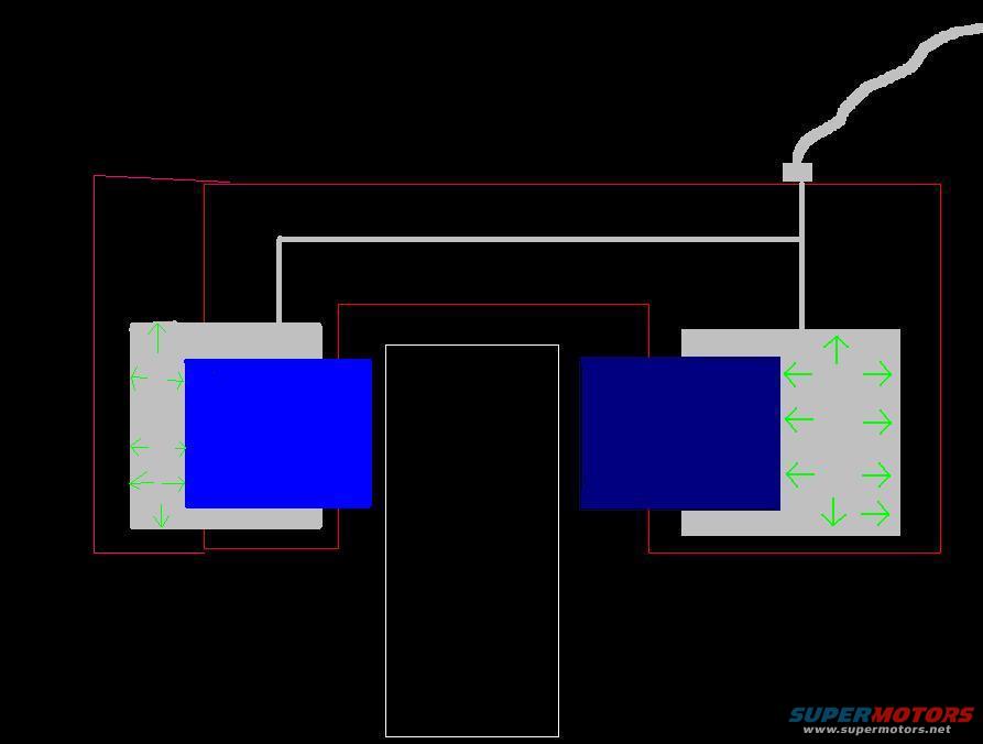
Simple conceptual schematic showing two boxes with directional arrows connected by a cable around a center block.
Part of 1986-1995 Suzuki Samurai Schematics
This document is a hand-drawn or computer-drawn schematic image with no text content whatsoever. It depicts what appears to be a mechanical or fluid-flow concept: two blue rectangular blocks (possibly representing pistons, based on the filename 'pistons-2.JPG') positioned on either side of a central white rectangular outline. Gray shaded areas surround the blue blocks, marked with numerous green arrows indicating direction of motion, force, or flow, arrows point inward toward the center on the right block and outward/up-down on the left block. Gray lines (possibly hoses, wires, or linkages) run from the tops of both blocks and join together, leading up to a small gray fitting at the top right, from which a wavy gray line (possibly a cable or hose) exits the frame. Thin red rectangular outlines enclose sections of the assembly, possibly denoting housings or boundaries. Because the diagram contains no labels, dimensions, part numbers, or captions, a reader can only infer general concept information (e.g., relative motion or flow direction of two piston-like elements) rather than specific service data. It was uploaded to a 1987 Suzuki Samurai gallery, but nothing in the image confirms or denies that application.
Is this accurate? Sign in to help verify it.
Frequently asked questions
- Does this schematic contain any part numbers, torque specs, or fuse information?
- No. The diagram contains no text at all, no part numbers, specifications, labels, or captions are visible.
- What does the diagram appear to show?
- Two blue rectangular blocks (piston-like elements) on either side of a central white rectangle, with green arrows indicating direction of movement or flow, and gray lines joining at a fitting with a wavy line exiting the top right.
- What do the green arrows indicate?
- The green arrows in the gray areas around the blue blocks show directions, on the right block they point inward and outward horizontally with up/down arrows at the corners; on the left block they point left and up/down, suggesting motion or flow direction, though the diagram itself does not label their meaning.
- Can this diagram be used to confirm applicability to a specific vehicle?
- No. The document shows no year, make, model, or engine information.

No comments yet.