Home/
Registry/
Suzuki/
Samurai/
1986-1995/
“Little Blue”/
Photo
supermotors.net/registry/media/420675
Suzuki Samurai EFI Ignition Circuit Schematic - ECM Pins & Wire Colors
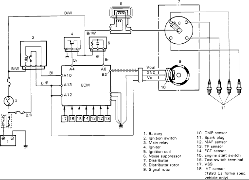
Schematic of the ignition and engine control system showing the ECM, distributor, spark plugs and sensors with a numbered component legend.
Part of 1986-1995 Suzuki Samurai Schematics
This document is a scanned ignition circuit schematic for a fuel-injected Suzuki Samurai. It shows the complete ignition system wiring: battery (1) and ignition switch (2) feeding a main relay (3), igniter (4), ignition coil (5), and noise suppressor (6), all connected to the ECM. The distributor assembly (7) is shown with its rotor (8), and a signal rotor (9) with CMP sensor (10) provides crank/cam position signals; four spark plugs (11) are fed from the distributor cap. Wire color codes are labeled: B/W, Br/W, B/R, Bl, Bl/B, Or, and Br. ECM terminals are identified as A4, A8, A10, A12, A13, and B3, plus a lower connector row numbered 12-18. A legend identifies 18 components including the MAF sensor (with Vout, GND, and VB terminals), TP sensor, ECT sensor, engine start switch, test switch terminal, VSS, and IAT sensor, the last noted as applying to 1993 California-spec vehicles only. A reader can learn the wiring paths, wire colors, ECM pin assignments, and sensor inputs involved in the ignition system, useful for diagnosing no-spark conditions or tracing ignition-related circuits.
Is this accurate? Sign in to help verify it.
Frequently asked questions
- What ECM terminals are used in the Samurai ignition circuit?
- The schematic shows ECM terminals A4 (Or wire), A8 (Br wire), A10 (Bl wire), A13 (Bl/B wire), A12, and B3, plus a lower connector row with pins numbered 17, 16, 15, 14, 13, 12, and 18.
- What wire colors are used in this ignition circuit?
- Visible wire color codes include B/W, Br/W, B/R, Bl, Bl/B, Or, and Br.
- What components are in this ignition system?
- The legend lists: battery, ignition switch, main relay, igniter, ignition coil, noise suppressor, distributor, distributor rotor, signal rotor, CMP sensor, spark plugs, MAF sensor, TP sensor, ECT sensor, engine start switch, test switch terminal, VSS, and IAT sensor.
- Does this schematic apply to all model years?
- The document notes that the IAT sensor (item 18) applies to 1993 California-spec vehicles only; no other year applicability is stated.
- What are the MAF sensor terminals shown?
- The MAF sensor connector shows three terminals: Vout, GND, and VB.
Comments
More from this build














No comments yet.