Ford Bronco Exhaust System Exploded Diagram - Catalytic Converter & Muffler

Reference · 1992-1996 BroncoAll 169 exploded parts diagrams
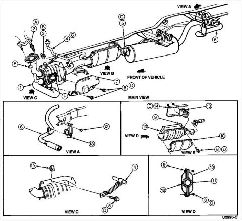






Exploded parts diagram of an exhaust system showing pipes, converter, muffler and heat shields with numbered callouts.
Part of 1992-1996 Ford Bronco Exploded Parts Diagrams
This document is an exploded parts diagram of a complete exhaust system, drawn as a main isometric view of the exhaust routed along the vehicle frame plus four detail insets (View A, View B, View C, and View D). The main view shows the exhaust manifold connection, catalytic converter assembly, muffler, heat shield, tailpipe, and associated hangers and hardware, with numbered callouts 1 through 15 and lettered callouts A through G identifying individual components and fasteners. Directional arrows indicate the front of the vehicle and the viewing angle for each detail inset. View A details a tailpipe hanger and bracket (callouts 6, 12, 13); View B shows the catalytic converter assembly with its shields and fasteners (callouts 9, 10, 13, 14, 8/D, E); View C shows the inlet pipe, insulator/hanger, and support bracket (callouts 15, 4, 8/D); and View D shows a cross-section of the converter shield assembly (callouts 9, 10, 11, 8/D). The drawing carries the Ford illustration reference number U2990-C. No text legend, part numbers, or torque specifications accompany the callouts on this page, so a companion legend page would be needed to identify each numbered part.
Is this accurate? Sign in to help verify it.
Frequently asked questions
- What does this diagram show?
- It is an exploded parts diagram of the exhaust system, including the catalytic converter, muffler, pipes, heat shields, hangers, and mounting hardware, shown in a main view plus four detail views (A, B, C, and D).
- How are the parts identified in the diagram?
- Parts are identified with circled numbered callouts (1 through 15) and circled lettered callouts (A through G), but no text legend is included on this page to name each part.
- What do the detail views cover?
- View A shows a tailpipe hanger/bracket area (callouts 6, 12, 13); View B shows the catalytic converter assembly (callouts 9, 10, 13, 14, 8/D, E); View C shows the front inlet pipe and support bracket (callouts 15, 4, 8/D); View D shows the converter shield assembly (callouts 9, 10, 11, 8/D).
- Which direction is the front of the vehicle in the main view?
- An arrow labeled 'FRONT OF VEHICLE' points toward the right side of the main view.
- Is there a reference number on the drawing?
- Yes, the illustration is marked U2990-C in the lower right corner.






No comments yet.