Ford Bronco Fuel Pump Sender & Reservoir Diagram - Wiring & Fuel Flow (A12768-E)

Reference · 1992-1996 BroncoAll 169 exploded parts diagrams
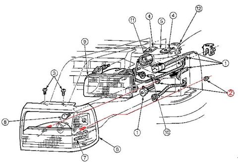
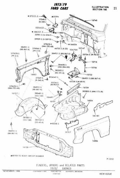
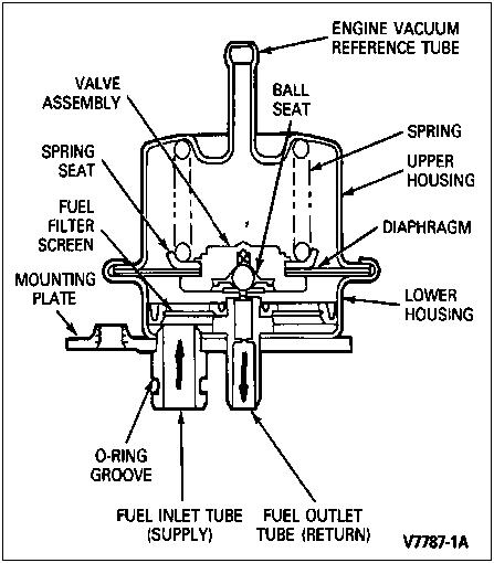
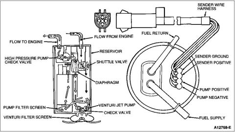






Diesel/EFI in-tank fuel delivery module cutaway showing high-pressure pump check valve, shuttle valve, diaphragm, venturi jet pump, filter screens, and sender wire harness terminal layout.
Part of 1992-1996 Ford Bronco Exploded Parts Diagrams
This document is a labeled cutaway/exploded diagram of a Ford in-tank fuel pump module (fuel delivery module) and sending unit assembly, uploaded to accompany a 1992 Ford Bronco. The left portion shows a cross-section of the pump reservoir, with callouts identifying internal components and fuel flow paths: flow to engine, flow from engine, the high pressure pump check valve, the reservoir, shuttle valve, diaphragm, pump filter screen, venturi jet pump, check valve, and venturi filter screen. Arrows within the cutaway indicate the direction of fuel flow through the reservoir. The right portion shows the complete sender/pump hanger assembly as installed through the tank flange, with the sender wire harness, an electrical connector (shown in end view with four terminals), and labels for the fuel return line, fuel supply line, and the four electrical connections: sender ground, sender positive, pump positive, and pump negative. The Ford illustration reference number A12768-E appears in the lower right corner. A reader can learn the internal layout of the reservoir-style fuel pump module, how fuel circulates through it, and how to identify the supply, return, and each electrical terminal on the sender assembly.
Is this accurate? Sign in to help verify it.
Frequently asked questions
- What are the four electrical connections on the fuel pump sender assembly?
- The diagram labels them as sender ground, sender positive, pump positive, and pump negative, all part of the sender wire harness.
- What components are inside the fuel pump reservoir?
- The cutaway shows a high pressure pump check valve, shuttle valve, diaphragm, pump filter screen, venturi jet pump, check valve, and venturi filter screen inside the reservoir.
- Which lines carry fuel to and from the engine on this assembly?
- The reservoir cutaway shows 'flow to engine' and 'flow from engine' ports, and the hanger assembly labels the fuel supply and fuel return lines.
- What filters the fuel before the pump in this module?
- The diagram shows a pump filter screen and a venturi filter screen at the bottom of the reservoir assembly.
- Is there a Ford illustration reference number on this diagram?
- Yes, the diagram is marked A12768-E in the lower right corner.






No comments yet.