Ford Bronco Overhead Console Exploded Parts Diagram - Roof Console Assembly

Reference · 1992-1996 BroncoAll 169 exploded parts diagrams


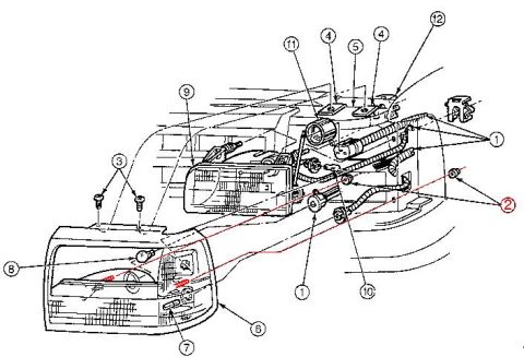
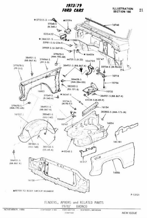

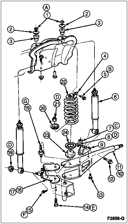
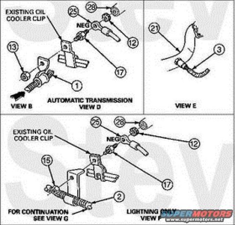
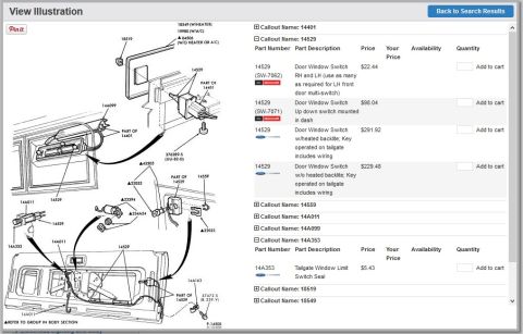
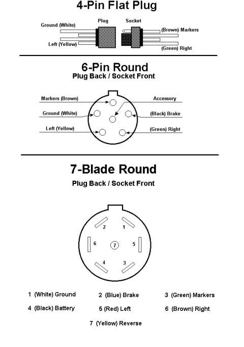
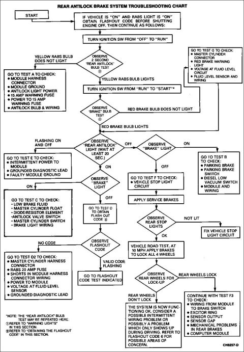
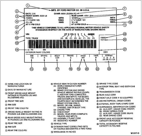



Exploded parts diagram of an overhead console assembly with numbered brackets, housing and lamp components.
Part of 1992-1996 Ford Bronco Exploded Parts Diagrams
This document is an exploded parts diagram of an overhead console assembly for a Ford Bronco, showing how the console components mount to the vehicle's roof/headliner area. Seven numbered callouts identify parts, but no legend, part names, or part numbers are printed on the page. Callout 2 points to a mounting bracket/plate that attaches to the roof structure (shown at top of the drawing). Callout 7 identifies a wiring harness with connectors that services the console. Callout 1 marks the main overhead console housing, which includes a map light lens area and storage/display sections. Callout 5 points to a smaller housing or lamp assembly, callout 6 identifies a component with two round openings (likely a dual map lamp or dome light body), callout 3 marks a rear console trim panel or bin with a grille-textured surface, and callout 4 points to a lens or cover at the bottom of the diagram. Arrows show each numbered part's position relative to the assembly. A reader can learn the relative assembly order and mounting relationship of the overhead console pieces, though part names and numbers must be obtained from an accompanying legend page (not present in this scan).
Is this accurate? Sign in to help verify it.
Frequently asked questions
- What does this diagram show?
- An exploded view of an overhead console assembly, showing seven numbered components including the roof mounting bracket, main console housing, wiring harness, lamp assemblies, trim panel, and lens, with arrows indicating how they fit together.
- How many parts are identified in the overhead console diagram?
- Seven parts are called out with numbers 1 through 7.
- Does the diagram include part numbers or names?
- No. Only numeric callouts (1-7) appear; there is no legend, part name list, or part number visible on this page.
- Which callout identifies the wiring harness?
- Callout 7 points to the wiring harness with connectors shown near the middle-right of the diagram.
- Which callout is the main console housing?
- Callout 1 points to the large main overhead console housing in the center of the diagram.






No comments yet.