Home/
Registry/
Ford/
Taurus/
1996-1999/
1997 Ford Taurus/
Photo
supermotors.net/registry/media/267365
1997 Ford Taurus HVAC Vacuum Diagram - A/C Heater Door Motors & Part Numbers

Reference · 1996-1999 TaurusAll 17 exploded parts diagrams






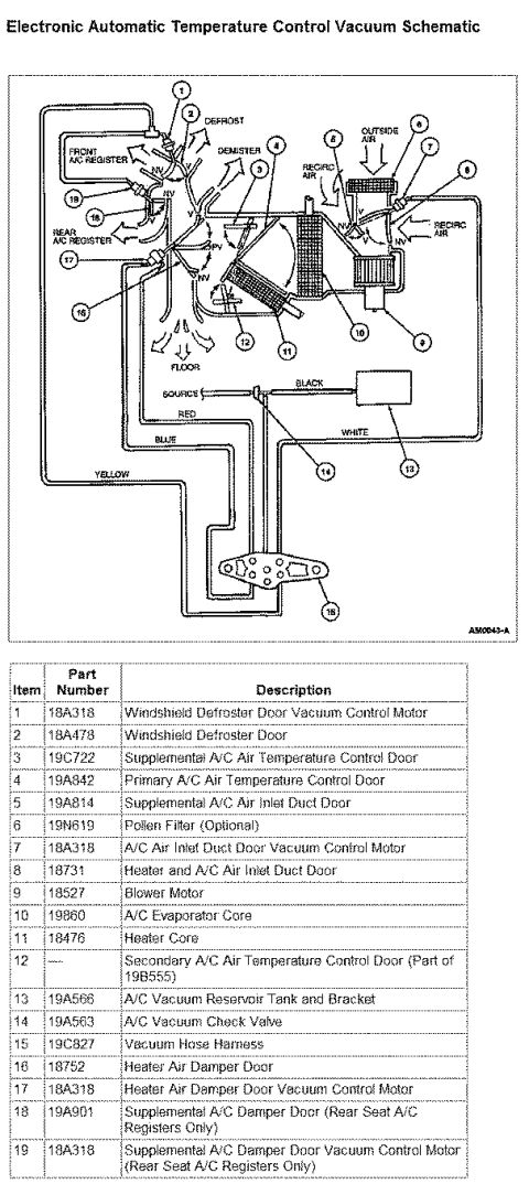

Ford A/C-heater airflow and vacuum-control schematic with 19-item part-number legend: defroster/temperature/inlet door vacuum motors (18A318), evaporator core 19860, heater core 18478, vacuum reservoir 19A566.
Part of 1996-1999 Ford Taurus Exploded Parts Diagrams
This document is a Ford heater/air-conditioning (HVAC) vacuum and airflow schematic with an accompanying 19-item parts legend (diagram reference AM0043-A). The exploded/schematic drawing shows air paths through the climate control case, defrost, demister, floor, front and rear A/C registers, outside air and recirculated air inlets, along with the vacuum hose harness routing identified by hose colors (black, red, white, blue, yellow) from the vacuum source to the reservoir tank, check valve, and vacuum control motors (marked NV/PV). The table lists each callout number with its Ford base part number and description, covering the windshield defroster door and its vacuum motor (18A318), primary and supplemental A/C air temperature control doors (19A842, 19C722), air inlet duct doors (19A814, 18731), an optional pollen filter (19N619), blower motor (18527), A/C evaporator core (19860), heater core (18476), vacuum reservoir tank and bracket (19A566), vacuum check valve (19A563), vacuum hose harness (19C827), heater air damper door (18752) and its motor, and supplemental A/C damper door components used with rear-seat A/C registers only (19A901). A reader can identify HVAC door functions, vacuum motor locations, hose color coding, and Ford part numbers for repair or diagnosis.
Is this accurate? Sign in to help verify it.
Frequently asked questions
- What part number is the blower motor in this diagram?
- Item 9, part number 18527, is the Blower Motor.
- What vacuum hose colors are shown in the HVAC vacuum harness?
- The diagram labels black, red, white, blue, and yellow vacuum hoses running from the source through the system.
- What part number is the A/C vacuum check valve and reservoir?
- The A/C Vacuum Check Valve is 19A563 (item 14) and the A/C Vacuum Reservoir Tank and Bracket is 19A566 (item 13).
- Which components apply only to rear seat A/C registers?
- Item 18, Supplemental A/C Damper Door (19A901), and item 19, Supplemental A/C Damper Door Vacuum Control Motor (18A318), are noted as Rear Seat A/C Registers Only.
- Is a pollen filter shown in this HVAC diagram?
- Yes, item 6 is a Pollen Filter, part number 19N619, listed as optional and located at the outside air inlet.


No comments yet.