Home/
Registry/
Ford/
Taurus/
1996-1999/
1997 Ford Taurus/
Photo
supermotors.net/registry/media/497270
1997 Ford Taurus Front Suspension Exploded Parts Diagram - Strut, Knuckle, Sway Bar

Reference · 1996-1999 TaurusAll 17 exploded parts diagrams


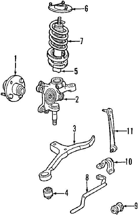
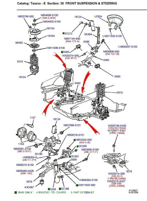


Exploded-view front suspension drawing with numbered components including hub, knuckle, coil spring, control arm and stabilizer bar.
Part of 1996-1999 Ford Taurus Exploded Parts Diagrams
This document is an exploded parts diagram of a front suspension assembly, uploaded to a gallery for a 1997 Ford Taurus. The illustration contains eleven numbered callouts pointing to individual components but includes no legend, part numbers, or descriptive text. Based on the drawings themselves: callout 1 points to a wheel hub/bearing assembly with studs; callout 2 points to the steering knuckle; callout 3 points to the lower control arm; callout 4 points to a control arm bushing; callout 5 points to the lower spring seat/insulator area of the strut; callout 6 points to the upper strut mount; callout 7 points to the coil spring and strut assembly; callout 8 points to the stabilizer (sway) bar; callout 9 points to a stabilizer bar bushing; callout 10 points to the stabilizer bar bracket and bushing; and callout 11 points to the stabilizer bar link. A reader can learn the relative arrangement and assembly order of the front suspension components and identify each part by its numbered position, though no textual identification, torque specifications, or part numbers are provided within the document itself.
Is this accurate? Sign in to help verify it.
Frequently asked questions
- What does this diagram show?
- It is an exploded-view parts illustration of a front suspension assembly with eleven numbered callouts identifying components such as the hub, steering knuckle, control arm, strut/coil spring, upper strut mount, and stabilizer bar hardware.
- Does the diagram include part numbers or a parts legend?
- No. The diagram contains only numbered callouts (1 through 11); no part numbers, names, or legend text appear in the document.
- How many components are identified in the diagram?
- Eleven components are called out, numbered 1 through 11.
- Which callout points to the coil spring and strut assembly?
- Callout 7 points to the coil spring/strut assembly, with callout 6 indicating the upper strut mount above it and callout 5 indicating the lower area of the strut.
No comments yet.