Home/
Registry/
Ford/
Taurus/
1996-1999/
1997 Ford Taurus/
Photo
supermotors.net/registry/media/626804
Ford Taurus 16 & 18 Gallon Fuel Tank Diagram - Fuel Pump & EVAP Part Numbers

Reference · 1996-1999 TaurusAll 17 exploded parts diagrams




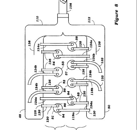
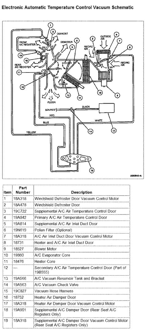

Ford 16-gallon fuel tank assembly exploded view with part numbers for the evaporative emission valves, fuel pump module and fuel pressure/vacuum transducer.
Part of 1996-1999 Ford Taurus Exploded Parts Diagrams
This scanned service reference page shows exploded/annotated diagrams of two Ford fuel tanks: a 16 gallon tank (figure code IR98S10F) and an 18 gallon tank (figure code V9903-A). The 16 gallon tank illustration labels the vapor vent valve (part of the fuel control valve assembly), fuel pressure transducer, fuel pump, fuel vent hose, fuel filler hose, and fuel control valve. The 18 gallon tank illustration uses numbered callouts 1 through 7 and includes an installation note stating that the transducer must be rotated 90 degrees from its installed position to its locked position. A parts legend table identifies each callout with Ford base part numbers: 9B593 Evaporative Emission Valve (68 liter/18 gallon tank only), 9002 Fuel Tank, 9G332 Evaporative Emission Tube Shut Off Valve, 9B593 Evaporative Emission Valve, 9C052 Fuel Tank Pressure/Vacuum Transducer, 9H308 Fuel Pump Module, and 9S278 Rear Fuel Supply Return and Vapor Tube. A reader can learn the location and identity of fuel tank components, distinguish which evaporative emission valve applies only to the 18 gallon tank, and understand the transducer locking procedure. The document was filed by an owner for a 1997 Ford Taurus; the document itself does not state a year or model.
Is this accurate? Sign in to help verify it.
Frequently asked questions
- What components are labeled on the 16 gallon fuel tank diagram?
- The 16 gallon tank diagram labels the vapor vent valve (part of the fuel control valve assembly), fuel pressure transducer, fuel pump, fuel vent hose, fuel filler hose, and fuel control valve.
- What is the part number for the fuel pump module?
- The fuel pump module is item 6 with part number 9H308.
- How is the fuel tank pressure/vacuum transducer locked in place?
- The diagram notes that from the installed position, the transducer is rotated 90 degrees to the locked position.
- Which evaporative emission valve applies only to the 18 gallon tank?
- Item 1, part number 9B593, is the Evaporative Emission Valve used on the 68 liter (18 gallon) tank only.
- What part number identifies the fuel tank itself?
- The fuel tank is item 2, part number 9002.



No comments yet.