Home/
Registry/
Ford/
Taurus/
1996-1999/
1999 Ford Taurus/
Photo
supermotors.net/registry/media/910041
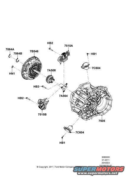
Ford Clutch & Manual Transaxle Exploded Parts Diagram - 7B546, 7A508, 7505
Reference · 1996-1999 TaurusAll 17 exploded parts diagrams






Exploded parts diagram of a clutch and manual transaxle assembly with Ford part number callouts.
Part of 1996-1999 Ford Taurus Exploded Parts Diagrams
This document is an official Ford exploded parts illustration (render) depicting a clutch and manual transaxle assembly. It shows the pressure plate/clutch disc assembly (callout 7B546) with associated snap ring/retainer parts (7064A, 7064B), a clutch release bearing (7A508), release lever/fork components (7A564), slave/actuator-related parts (7515A, 7515B), the transaxle case assembly (7505), and two identical sensor/switch or plug components (7C604) shown at the top and bottom of the case. Hardware fasteners are indicated with codes HB1, HB2 (used twice), HB3, and a nut HN1. Dashed leader lines show the assembly relationships between the clutch components and the transaxle housing. The illustration footer carries the reference numbers 3080005, date code 01-2011, code 20HDEX, and drawing number F0258220-02, with a copyright notice reading '© Copyright, 2011, Ford Motor Company Limited.' A reader can use this diagram to identify Ford basic part group numbers for clutch and transaxle service parts and to see how the components fit together, though no descriptive part names, torque specs, or vehicle model applicability text appear on the drawing itself.
Is this accurate? Sign in to help verify it.
Frequently asked questions
- What is the callout number for the transaxle case assembly in this diagram?
- The main transaxle/transmission assembly is labeled 7505.
- What part number is shown for the clutch pressure plate/disc assembly?
- The clutch assembly at the upper left is labeled 7B546, with related parts 7064A and 7064B nearby.
- What fastener codes appear on this Ford exploded diagram?
- Fastener callouts HB1, HB2 (shown twice), HB3, and nut HN1 are indicated.
- When was this Ford illustration published?
- The footer shows a date code of 01-2011 and the caption reads '© Copyright, 2011, Ford Motor Company Limited.'
- What reference/drawing numbers identify this illustration?
- The footer lists 3080005, 20HDEX, and drawing number F0258220-02.




No comments yet.