Home/
Registry/
Ford/
Crown Victoria/
1998-2011/
“texasvic”/
Photo
supermotors.net/registry/media/272153
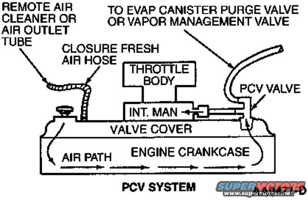
Ford PCV System Diagram - Crankcase Ventilation Air Flow Schematic (AA0471-D)
Reference · 1998-2011 Crown VictoriaAll 11 schematics
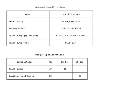

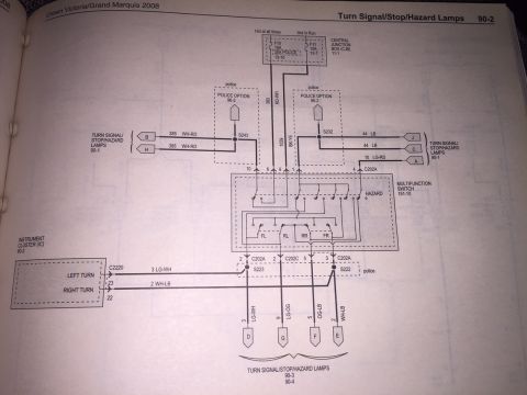
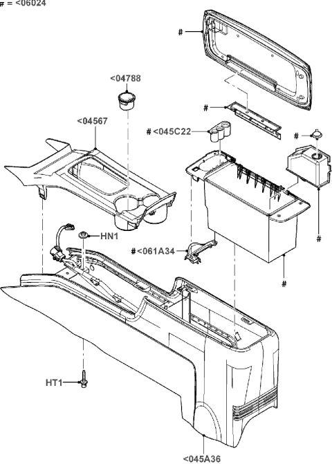
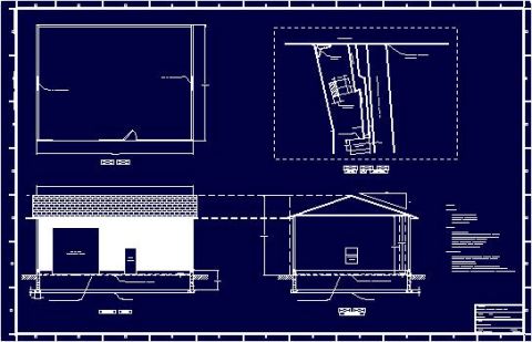
Schematic of the PCV crankcase ventilation system routing air from the air cleaner through the throttle body, PCV valve and vapor management valve.
Part of 1998-2011 Ford Crown Victoria Schematics
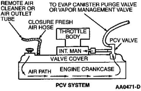
This document is a labeled schematic diagram of a Positive Crankcase Ventilation (PCV) system, uploaded to a 2000 Ford Crown Victoria gallery. The diagram illustrates the flow of air through the engine's crankcase ventilation circuit. Fresh air enters from a remote air cleaner or air outlet tube through a closure fresh air hose into the valve cover. Arrows labeled 'AIR PATH' show the air traveling down into the engine crankcase, circulating through it, and exiting through the PCV valve mounted at the opposite end of the valve cover. From the PCV valve, vapors are drawn into the intake manifold (labeled 'INT. MAN.') beneath the throttle body. A separate hose at the PCV valve area routes to the EVAP canister purge valve or vapor management valve. The diagram is captioned 'PCV SYSTEM' and carries the illustration reference code AA0471-D. A reader can learn the overall airflow direction of the PCV system, the relative locations of key components (air cleaner connection, fresh air hose, valve cover, crankcase, PCV valve, intake manifold, throttle body), and how the PCV system ties into the evaporative emissions system. The document itself does not state a specific year, model, or engine application.
Is this accurate? Sign in to help verify it.
Frequently asked questions
- How does air flow through the PCV system in this diagram?
- Fresh air enters from the remote air cleaner or air outlet tube through the closure fresh air hose into the valve cover, flows down into the engine crankcase (shown by 'AIR PATH' arrows), then exits through the PCV valve into the intake manifold near the throttle body.
- Where is the PCV valve located according to this schematic?
- The PCV valve is shown mounted on the valve cover, connected to the intake manifold ('INT. MAN.') just below the throttle body.
- What else connects near the PCV valve in this diagram?
- A hose routes from the PCV valve area to the EVAP canister purge valve or vapor management valve.
- What is the reference code on this diagram?
- The illustration is marked AA0471-D and captioned 'PCV SYSTEM'.

No comments yet.