Home/
Registry/
Ford/
Crown Victoria/
1998-2011/
2001 Ford Crown Victoria/
Photo
supermotors.net/registry/media/549255
2001 Ford Crown Victoria A/C System Component Diagram (AM1175-B)

Reference · 1998-2011 Crown VictoriaAll 11 schematics
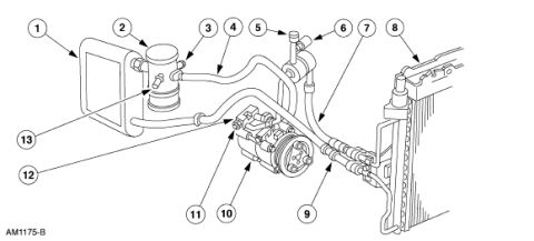

Air conditioning system layout schematic with numbered callouts identifying the compressor, condenser, accumulator, and hoses.
Part of 1998-2011 Ford Crown Victoria Schematics
This document is a line-art schematic (Ford illustration ID AM1175-B) showing the air conditioning refrigerant system components and plumbing of a vehicle, uploaded to the gallery of a 2001 Ford Crown Victoria. The drawing depicts, from left to right: a rectangular accumulator/canister assembly with attached lines (callouts 1, 2, 3, 13), refrigerant hoses/lines routing across the engine bay (callouts 4, 5, 6, 7), a belt-driven A/C compressor with clutch pulley and manifold fittings (callouts 10, 11, 12), a discharge/liquid line with fittings (callout 9), and the condenser mounted ahead of the radiator (callout 8). Thirteen numbered callout balloons identify individual components, but no legend or parts list is included in this scan, so the callout numbers cannot be matched to component names from this page alone (a companion page in the same album may contain the legend). No year, model, engine, torque, or part-number text appears other than the illustration code AM1175-B. A reader can learn the general layout and routing of the A/C system, how the lines connect the accumulator, compressor, and condenser, but must consult an accompanying legend for component identification.
Is this accurate? Sign in to help verify it.
Frequently asked questions
- What does this diagram show?
- It is a schematic of an air conditioning system, showing the accumulator, refrigerant lines, the belt-driven A/C compressor, and the condenser in front of the radiator, with 13 numbered callouts.
- Does the diagram include a legend identifying each numbered component?
- No. The scan shows only the numbered callout balloons (1 through 13) and the illustration code AM1175-B; no legend or component names are visible.
- What is the illustration reference code on this diagram?
- The drawing is labeled AM1175-B in the lower-left corner.
- How many components are called out in the diagram?
- Thirteen numbered callouts (1-13) identify components of the A/C system.

No comments yet.