Home/
Registry/
Ford/
Crown Victoria/
1998-2011/
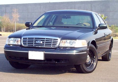
2002 Ford Crown Victoria/
Photo
supermotors.net/registry/media/437900
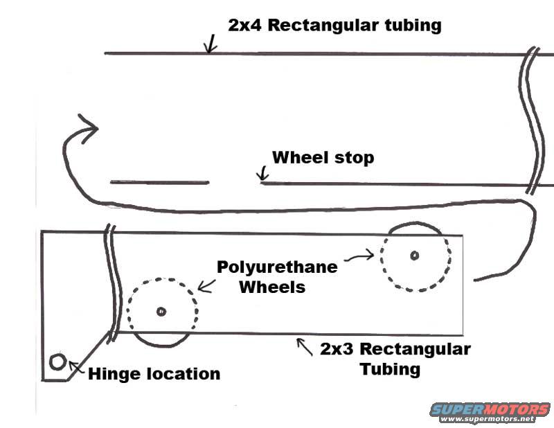
Slide-and-Flip Hinge Schematic - 2x4/2x3 Tubing & Polyurethane Wheels Diagram
Reference · 1998-2011 Crown VictoriaAll 11 schematics



Hand-drawn fabrication diagram of a folding rack showing 2x4 and 2x3 tubing, polyurethane wheels, wheel stop and hinge location.
Part of 1998-2011 Ford Crown Victoria Schematics
This document is a hand-drawn schematic sketch illustrating a slide-and-flip hinge mechanism, apparently a homemade/fabricated design (uploaded to a 2002 Ford Crown Victoria gallery, likely as a project reference). The drawing shows an outer channel or track made from 2x4 rectangular tubing, inside which a smaller sliding member made from 2x3 rectangular tubing travels. The 2x3 tubing carries two polyurethane wheels (shown as dashed circles with center axles) that roll inside the 2x4 tubing track. A 'wheel stop' is marked partway along the inside of the 2x4 tubing to limit wheel/slide travel. A hinge location is called out at the lower-left end of the 2x3 tubing member, indicated by a small circle (hinge pin/bolt hole). A curved arrow at the left of the drawing indicates the flip/rotation motion of the assembly once it reaches the end of its sliding travel. The sketch contains no dimensions beyond the nominal tubing sizes, no part numbers, no dates, and no vehicle-specific information. A reader can learn the basic concept and component arrangement for building a slide-and-flip hinge using rectangular steel tubing sections, polyurethane rollers, a travel stop, and a pivot point.
Is this accurate? Sign in to help verify it.
Frequently asked questions
- What materials are used for the slide-and-flip hinge track and slider?
- The outer track is made from 2x4 rectangular tubing, and the sliding member is made from 2x3 rectangular tubing.
- What type of wheels does the design use?
- Polyurethane wheels, shown mounted on the 2x3 rectangular tubing slider (two wheels are depicted).
- How is the slide travel limited?
- A 'wheel stop' is shown inside the 2x4 rectangular tubing track to stop the wheels at the end of travel.
- Where is the hinge located in this design?
- The hinge location is marked at the lower-left end of the 2x3 rectangular tubing member, indicated by a small circular hole.
- Does the diagram give exact dimensions or part numbers?
- No. It only specifies nominal tubing sizes (2x4 and 2x3 rectangular tubing) and shows no measurements, part numbers, or dates.

No comments yet.