Home/
Registry/
Ford/
Crown Victoria/
1998-2011/
“BricVic”/
Photo
supermotors.net/registry/media/438040
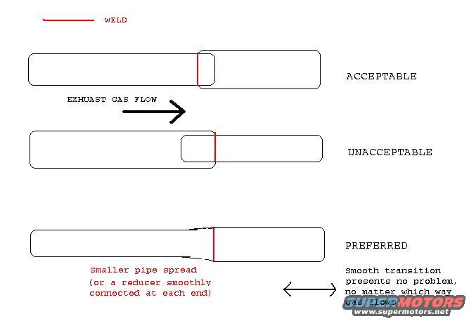
Exhaust Pipe Weld Joint Diagram - Acceptable vs. Preferred Slip Joint Direction
Reference · 1998-2011 Crown VictoriaAll 11 schematics
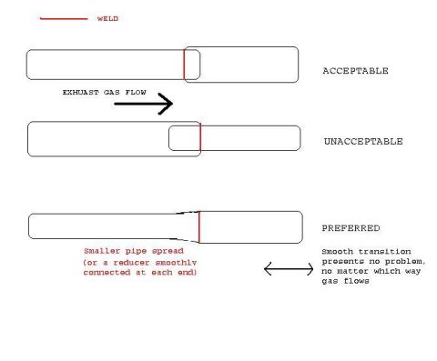


Schematic comparing acceptable, unacceptable and preferred exhaust pipe weld joints relative to gas flow.
Part of 1998-2011 Ford Crown Victoria Schematics
This is a hand-drawn schematic illustrating correct and incorrect methods of welding exhaust pipe joints, particularly where two pipes of different diameters are connected. A legend identifies red lines as welds, and an arrow labeled 'EXHUAST GAS FLOW' (sic) shows the direction of exhaust gas travel. Three joint configurations are shown: (1) ACCEPTABLE: the smaller upstream pipe slips inside the larger downstream pipe so gas flows smoothly from small to large; (2) UNACCEPTABLE: the joint is arranged so the overlap faces into the gas flow, creating a lip/edge against the flow direction; and (3) PREFERRED: the smaller pipe is spread (flared) to match the larger pipe, or a reducer is smoothly connected at each end, producing a smooth transition. A note explains that a smooth transition presents no problem no matter which way the gas flows. The document teaches exhaust fabricators how to orient slip-joint welds relative to exhaust flow to avoid flow disruption. It contains no vehicle-specific information, part numbers, dates, or measurements, it is a generic exhaust fabrication technique diagram applicable to any vehicle, uploaded in the context of a 2000 Ford Crown Victoria.
Is this accurate? Sign in to help verify it.
Frequently asked questions
- Which direction should exhaust pipes overlap at a welded slip joint?
- The acceptable configuration has the smaller upstream pipe slipped inside the larger downstream pipe, so exhaust gas flows from the small pipe into the large pipe without hitting an edge. The reverse orientation is shown as unacceptable.
- What is the preferred way to join two exhaust pipes of different sizes?
- The preferred method is to spread (flare) the smaller pipe to match the larger pipe, or use a reducer smoothly connected at each end, creating a smooth transition.
- Why is a smooth transition joint preferred?
- According to the diagram, a smooth transition presents no problem no matter which way the exhaust gas flows.
- How are welds indicated on this diagram?
- A legend shows that red lines on the pipe joints represent welds.

No comments yet.