Home/
Registry/
Ford/
Crown Victoria/
1998-2011/
“BricVic”/
Photo
supermotors.net/registry/media/438041
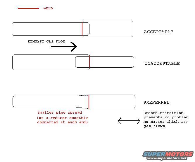
Exhaust Pipe Joint Welding Diagram - Acceptable vs. Preferred Transitions
Reference · 1998-2011 Crown VictoriaAll 11 schematics
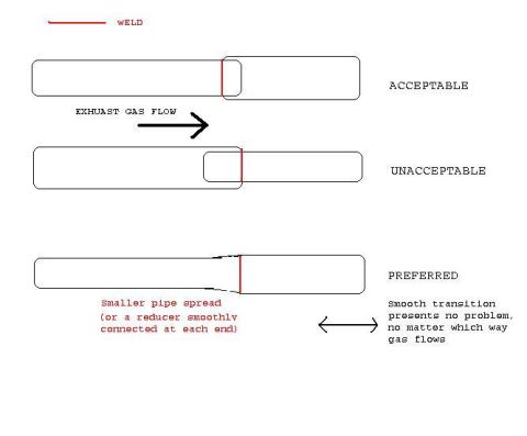


Schematic comparing acceptable, unacceptable and preferred exhaust pipe weld joints with notes on smooth transitions.
Part of 1998-2011 Ford Crown Victoria Schematics
This document is a simple hand-drawn schematic illustrating correct and incorrect methods of joining two exhaust pipes of different diameters by welding. A legend at the top indicates that red lines represent welds. Three joint configurations are shown relative to the direction of exhaust gas flow (labeled 'EXHUAST GAS FLOW' with an arrow). The first, labeled 'ACCEPTABLE,' shows the smaller pipe inserted into the larger pipe so gas flows from the smaller pipe into the larger one. The second, labeled 'UNACCEPTABLE,' shows the larger pipe positioned so gas flow encounters an abrupt internal step (the smaller pipe slipped inside against the flow direction). The third, labeled 'PREFERRED,' shows the smaller pipe spread (or a reducer smoothly connected at each end) to create a smooth taper into the larger pipe; a note explains that a smooth transition presents no problem no matter which way the gas flows, indicated by a double-headed arrow. A reader can learn general best practice for exhaust pipe joint orientation and welding: avoid abrupt steps facing the gas flow, and prefer a smoothly tapered transition. The diagram is generic and contains no vehicle-specific years, models, part numbers, or dimensions.
Is this accurate? Sign in to help verify it.
Frequently asked questions
- What is the preferred way to join a smaller exhaust pipe to a larger one?
- Spread the smaller pipe (or use a reducer smoothly connected at each end) so there is a smooth transition into the larger pipe, then weld the joint. The smooth transition presents no problem no matter which way the gas flows.
- What makes an exhaust pipe joint unacceptable in this diagram?
- A joint where the exhaust gas flow encounters an abrupt step, the smaller pipe slipped inside the larger pipe oriented against the direction of gas flow, is labeled unacceptable.
- What do the red lines in the diagram represent?
- The legend indicates the red lines represent welds.
- Does the flow direction matter for the preferred smooth-transition joint?
- No. The diagram states a smooth transition presents no problem no matter which way the gas flows.
No comments yet.