Home/
Registry/
Ford/
Crown Victoria/
1998-2011/
“BricVic”/
Photo
supermotors.net/registry/media/454350
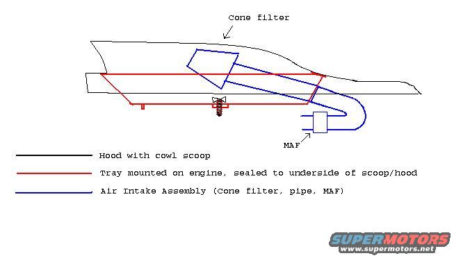
Cowl Scoop Cold Air Intake Schematic - Cone Filter, Sealed Tray & MAF Layout
Reference · 1998-2011 Crown VictoriaAll 11 schematics
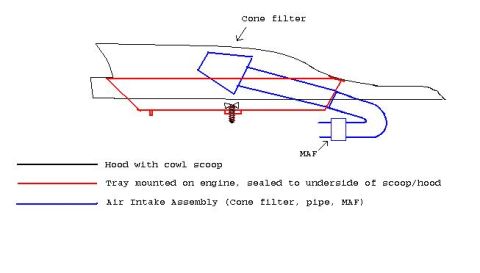


Schematic showing cold-air intake routing including cone filter, MAF and engine tray sealed to a cowl-scoop hood.
Part of 1998-2011 Ford Crown Victoria Schematics
This document is a hand-drawn schematic (line drawing) illustrating a homemade cowl-induction cold air intake (CAI) concept, uploaded to a 2000 Ford Crown Victoria gallery. The side-profile drawing shows a vehicle hood featuring a cowl scoop (drawn in black), a tray mounted on the engine and sealed to the underside of the scoop/hood (drawn in red), and an air intake assembly (drawn in blue) consisting of a cone filter positioned inside the tray/scoop area, an intake pipe that curves down and around, and a MAF (mass air flow) sensor located at the pipe's outlet. A color-coded legend at the bottom explains the three colored line groups. The drawing conveys how fresh air entering the cowl hood scoop would be captured in a sealed tray, drawn through the cone filter, routed through the pipe, past the MAF sensor, and into the engine intake. No dimensions, part numbers, torque values, wire colors, model years, or applicability information are given; the document is purely conceptual, showing the spatial arrangement and sealing strategy for a cowl-fed cold air intake. A small threaded fastener/spring is sketched at the tray, presumably indicating a mounting point, though it is unlabeled.
Is this accurate? Sign in to help verify it.
Frequently asked questions
- What are the main components shown in this cowl CAI schematic?
- A hood with cowl scoop (black), a tray mounted on the engine and sealed to the underside of the scoop/hood (red), and an air intake assembly consisting of a cone filter, pipe, and MAF sensor (blue).
- Where is the cone filter located in this design?
- The cone filter sits inside the tray area under the cowl scoop, at the upper end of the intake pipe.
- How is the tray integrated with the hood?
- The tray is mounted on the engine and sealed to the underside of the cowl scoop/hood, so scoop air is captured for the filter.
- Where is the MAF sensor positioned?
- The MAF is at the lower/outlet end of the intake pipe, after the pipe curves down and around from the cone filter.


No comments yet.