Home/
Registry/
Ford/
Crown Victoria/
1998-2011/
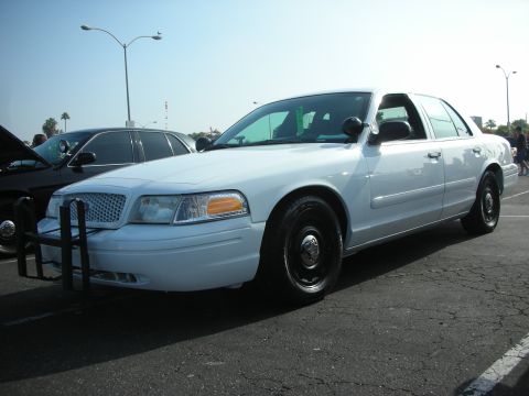
“The Trouper”/
Photo
supermotors.net/registry/media/151642
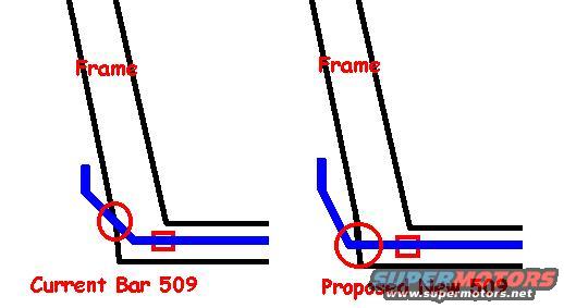
Bar 509 Frame Mounting Comparison Sketch - Current vs Proposed New 509 Diagram
Reference · 1998-2011 Crown VictoriaAll 11 schematics
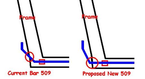

Simple comparison schematic of current Bar 509 versus a proposed bar routing relative to the frame.
Part of 1998-2011 Ford Crown Victoria Schematics
This is a simple hand-drawn schematic sketch comparing two mounting or routing configurations of a component labeled "509," apparently a bar, in relation to a vehicle frame. The image shows two side-by-side drawings. In each, black lines represent the vehicle frame (labeled "Frame" in red text), and a thick blue line represents the bar. Red circles and small red rectangles highlight points of interest where the blue bar meets or crosses the frame lines, presumably attachment or clearance points. The left drawing is labeled "Current Bar 509" and shows the blue bar bending and terminating near the frame junction, with the circled area at the bend and a small rectangle further along the horizontal run. The right drawing, labeled "Proposed New 509," shows the blue bar extending further, passing through or beyond the frame junction, with the red circle placed at the intersection point and a similar red rectangle on the horizontal section. The document contains no part numbers beyond "509," no dimensions, torque specs, or year/model identification. It was uploaded to a 1999 Ford Crown Victoria gallery, suggesting it illustrates a proposed modification (likely to a suspension or support bar) for that vehicle, though the drawing itself does not state applicability.
Is this accurate? Sign in to help verify it.
Frequently asked questions
- What does this diagram compare?
- It compares two configurations of a component labeled "509": the "Current Bar 509" on the left and a "Proposed New 509" on the right, both shown relative to the vehicle frame.
- What is the difference between the current and proposed 509 bar?
- In the current version, the blue bar bends and ends near the frame junction; in the proposed version, the bar extends further so that it passes through/beyond the frame junction point, as highlighted by the red circles.
- What do the red circles and rectangles indicate?
- They highlight areas of interest where the blue bar interacts with the frame, the circles mark the bar's bend/intersection with the frame, and the small rectangles mark a point along the horizontal frame section. The drawing does not label their exact meaning.
- Does the diagram give any dimensions or part numbers?
- No dimensions, torque values, or full part numbers are shown, only the labels "Frame," "Current Bar 509," and "Proposed New 509."
No comments yet.